Phase plate and an optical data recording/reproducing device
a phase plate and optical data technology, applied in the direction of optical recording/reproducing/erasing methods, instruments, polarising elements, etc., can solve the problems of not being able to disclose a concrete device structure, limiting the volume of recording, and not being able to use the device practically. , to achieve the effect of small size, high accuracy, and light weigh
- Summary
- Abstract
- Description
- Claims
- Application Information
AI Technical Summary
Benefits of technology
Problems solved by technology
Method used
Image
Examples
fifth embodiment
of Phase Plate
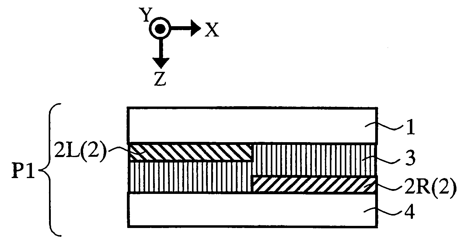
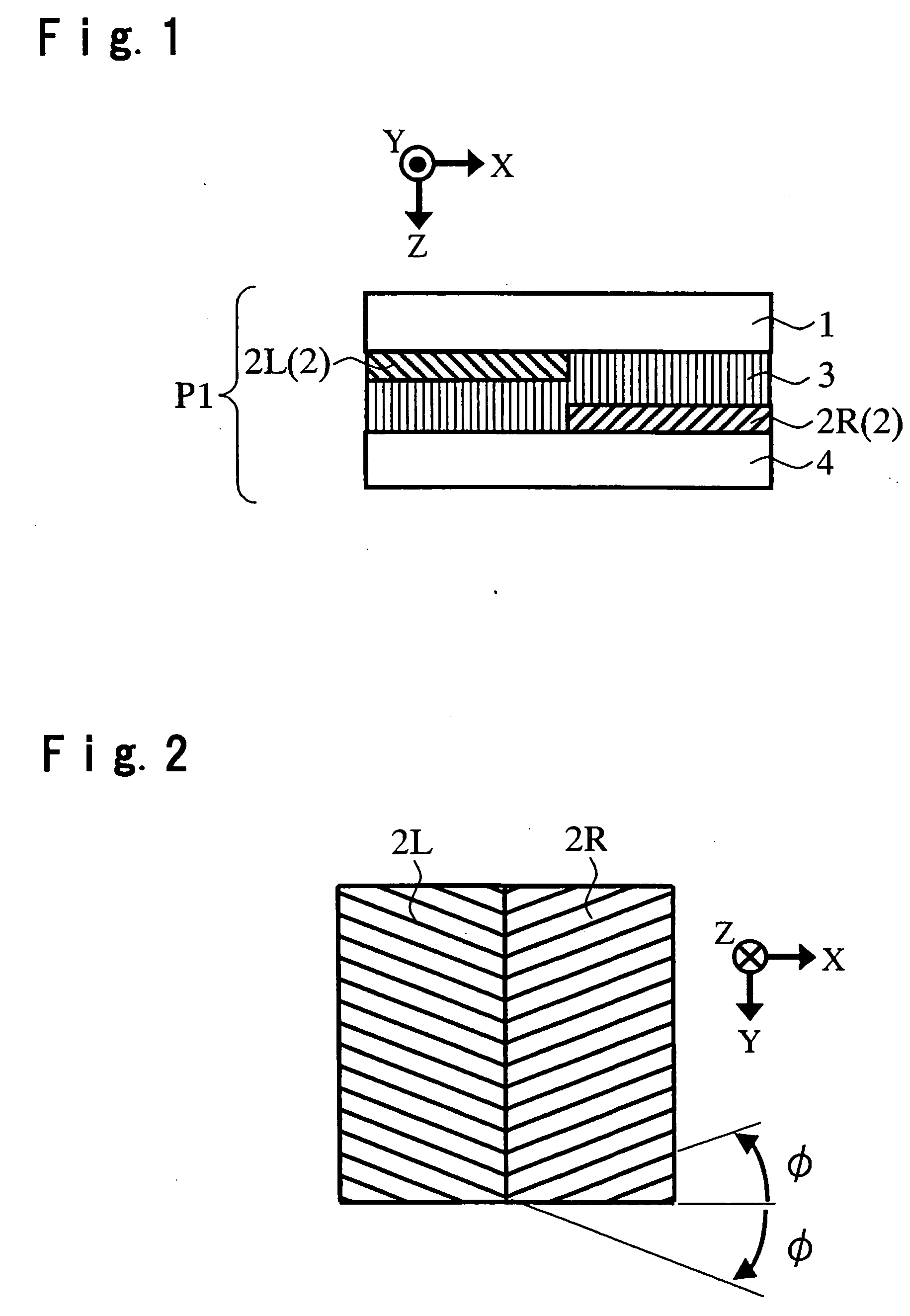
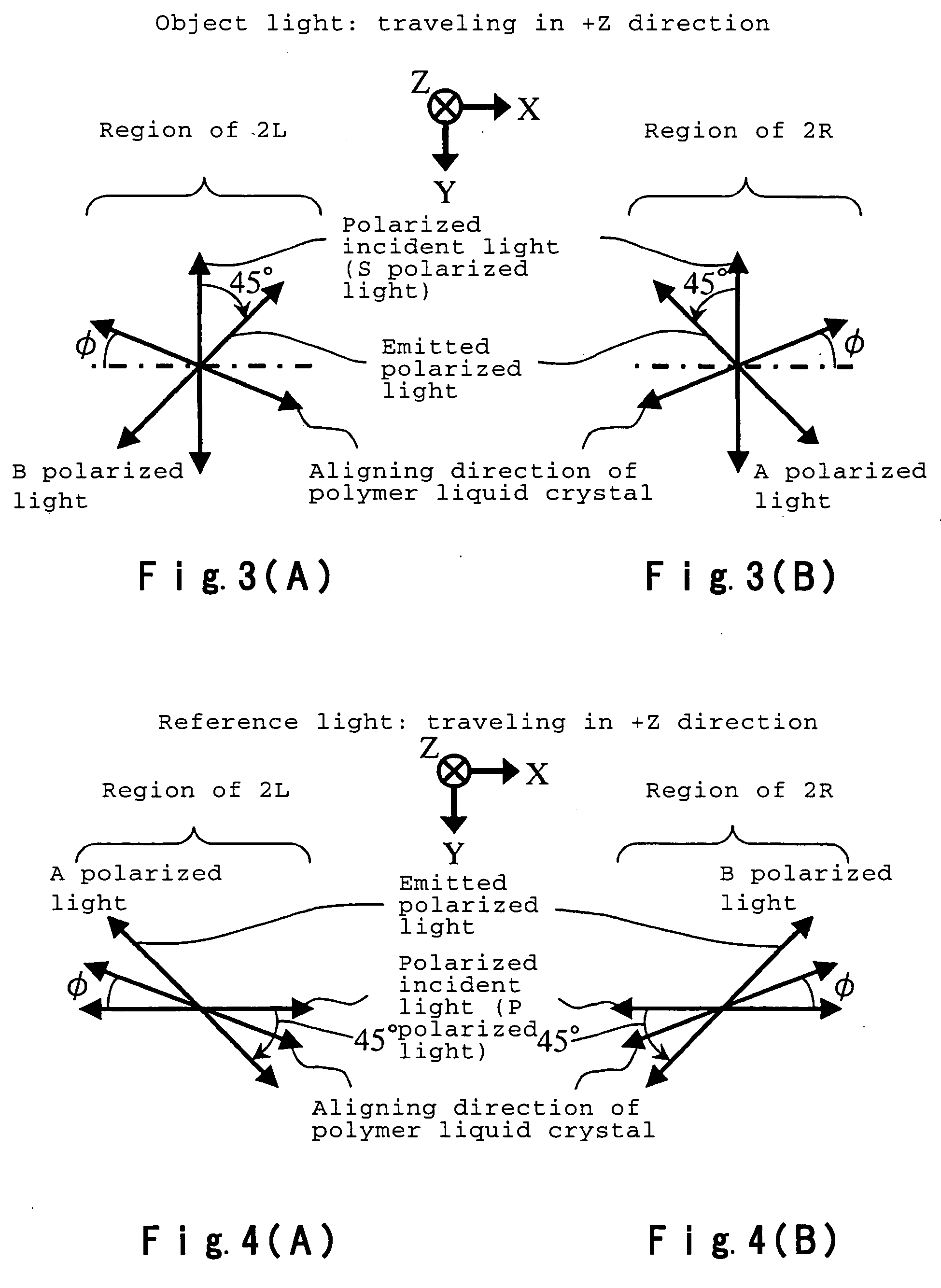
[0118] Now, description will be made as to a phase plate P5 as a fifth embodiment of the phase plate according to the present invention.
[0119] This phase plate is the same as the phase plates P1 to P4 as two-parted optical rotation plates according to the first to fourth embodiments except that the retardation value with respect to an incident light having a wavelength λs (λs≠λ), of each of the polymer liquid crystal films 2L, 2R, 6L, 7, 8L, 8R and the half-wave plates 5, 7 as constructional elements of the phase plates, is k×λs (where k is an integer of positive sign).
[0120] For example, assuming that λ=532 nm as the wavelength of the second harmonic wave of Nd: YAG laser and λs=660 nm as the oscillation wavelength of a semiconductor laser for DVD are given, when the retardation value is Rd=2.5×λ (i.e., m=2), Rd=2×λs (i.e., k=2).
[0121] Further, assuming that λ=430 nm as the wavelength of the harmonic wave of a semiconductor laser of the oscillation wavelength of 86...
first embodiment
of Polarizing Beam Splitter
[0129]FIG. 11 is a cross-sectional view of a polarizing beam splitter PB1 as a first embodiment of the polarizing beam splitter used in the optical data recording / reproducing device of the present invention. This polarizing beam splitter PB1 comprises transparent substrates 11, 12, polymer liquid crystal layers 11A, 12A provided between the transparent substrates 11, 12 and a homogeneous refractive index transparent material 13.
[0130] In this polarizing beam splitter PB1, an alignment layer is formed on each single surface of the transparent substrates 11, 12, the alignment layers are subjected to an aligning treatment and liquid crystal monomer is coated thereon followed by polymerization whereby polymer liquid crystal layers 11A having an ordinary refractive index no and an extraordinary refractive index ne (ne>no) are formed. In this case, the alignment layer on the transparent substrate 11 is subjected to an aligning treatment so that the direction of...
second embodiment
of Polarizing Beam Splitter
[0141] Now, explanation will be made as to a second embodiment of the polarized beam splitter used in the optical data recording / reproducing device of the present invention.
[0142]FIG. 12 is a cross-sectional view of a polarizing beam splitter PB2 according to the second embodiment of the present invention. The polarizing beam splitter PB2 is the same as the polarizing beam splitter PB1 in that the polymer liquid crystal layer 11A having an ordinary refractive index no and an extraordinary refractive index ne (ne>no) is formed on a single surface of a transparent substrate 11 and a blazed diffraction grating having a saw-tooth-like shape in cross-section and having a grating constant (pitch) L is formed by processing, but is different from the polarizing beam splitter PB1 in that the refractive index ns of the homogeneous refractive index transparent material to be filled in the recessed portions of the polymer liquid crystal layer 11A to form a homogeneou...
PUM
 Abstract
Description
Claims
Application Information
 - R&D
- Intellectual Property
- Life Sciences
- Materials
- Tech Scout
- Unparalleled Data Quality
- Higher Quality Content
- 60% Fewer Hallucinations
Browse by: Latest US Patents, China's latest patents, Technical Efficacy Thesaurus, Application Domain, Technology Topic, Popular Technical Reports.
© 2025 PatSnap. All rights reserved.Legal|Privacy policy|Modern Slavery Act Transparency Statement|Sitemap|About US| Contact US: help@patsnap.com


