

Optical disk device and method of control of an optical disk
a technology of optical disk and optical disk, which is applied in the direction of digital signal error detection/correction, instruments, recording signal processing, etc., can solve the problem of increasing the amount of data processed, and achieve the effect of suppressing the delay in processing due to the failure of access
- Summary
- Abstract
- Description
- Claims
- Application Information
AI Technical Summary
Benefits of technology
Problems solved by technology
Method used
Image

Examples
first embodiment
[0040] First Embodiment
[0041] Video devices comprising video players or video cameras using optical disks are becoming more and more popular. In recent years, optical disks have been made smaller in size and larger in storage capacity. As a result, the performance of optical disks has improved significantly.
[0042] The drive system of the optical disk is used to drive the optical disk and includes the CLV (constant linear velocity) system for driving the optical disk at a constant linear velocity and the CAV (constant angular velocity) system for driving the optical disk at a constant angular velocity.
[0043] When using an optical disk for a small sized video device such as a video camera, there are restrictions in the rotational performance of the spindle motor driving the optical disk. Due to this restriction, for example, even if an optical disk is formatted to be driven by a constant linear velocity on a recording medium of the video camera, due to the limits of performance of t...
second embodiment
[0047] Second Embodiment
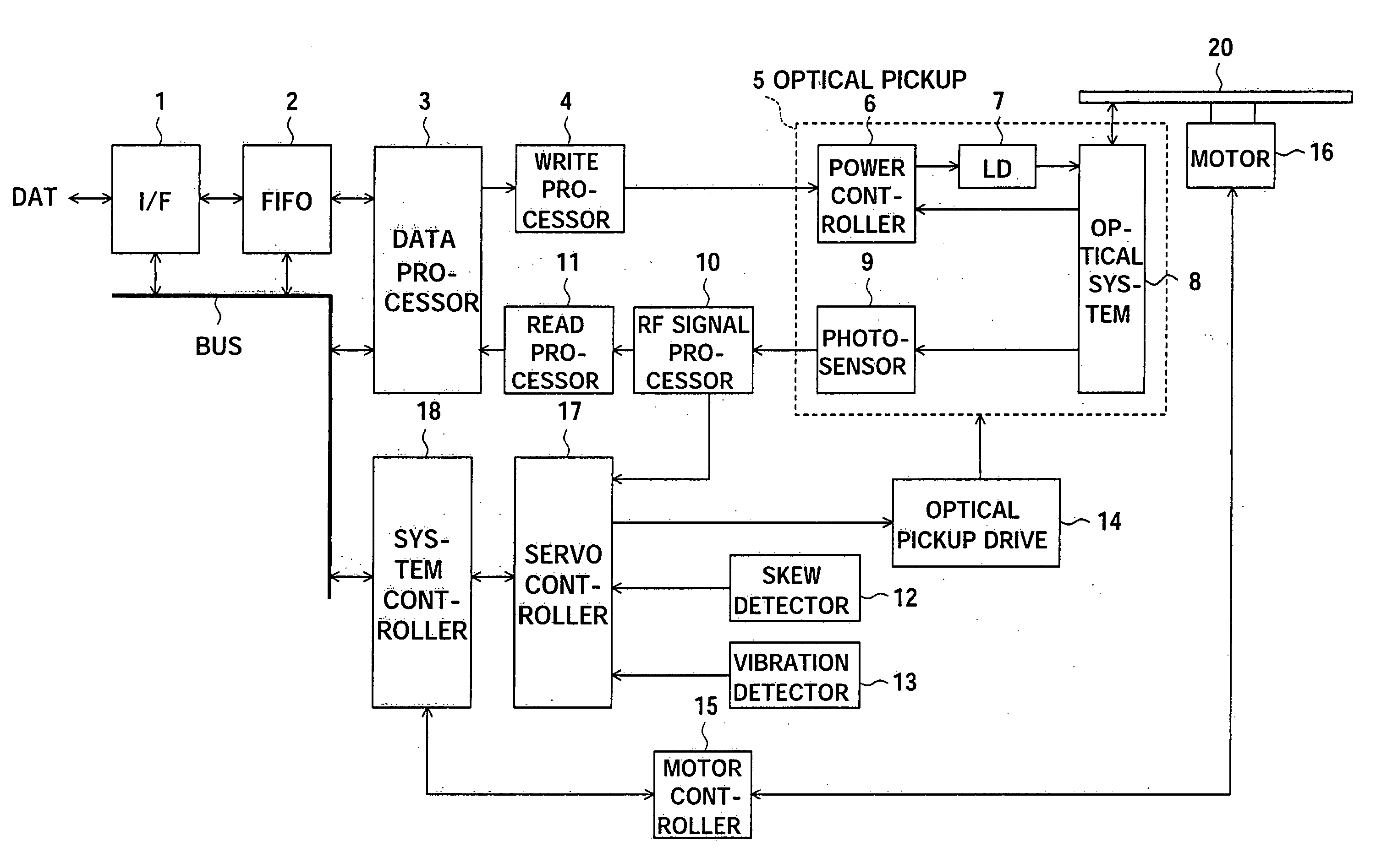
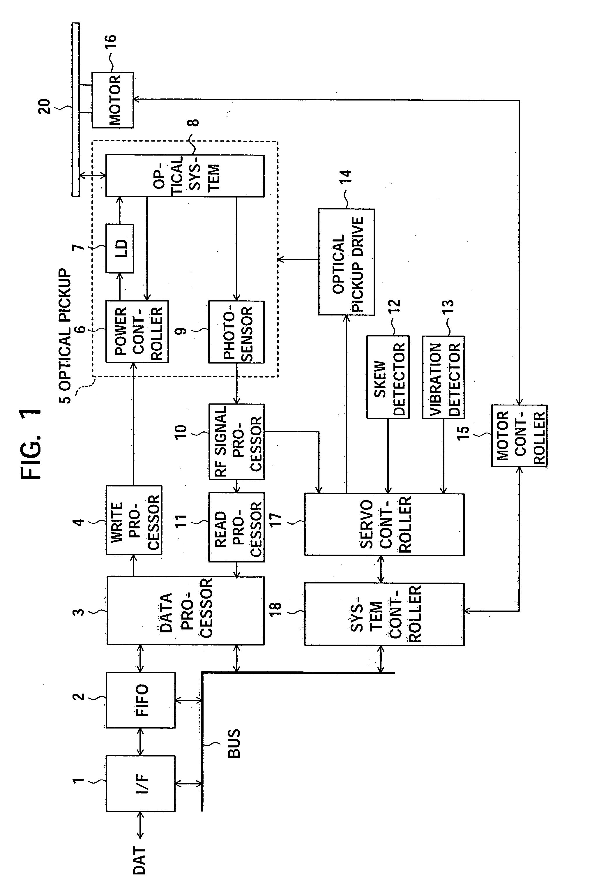
[0048]FIG. 1 is an example of a configuration of an optical disk device according to a first embodiment of the present invention.
[0049] The optical disk device shown in FIG. 1 has an interface 1, a FIFO unit 2, a data processor 3, a write processor 4, an optical pickup 5, an RF signal processor 10, a read processor 11, a skew detector 12, a vibration detector 13, an optical pickup drive 14, a motor controller 15, a spindle motor 16, a servo controller 17, and a system controller 18.
[0050] Further, the optical pickup 5 has a power controller 6, a laser diode 7, an optical system 8, and a photosensor 9.
[0051] In the above configuration, the motor 16 is an illustration of the rotational drive of the present invention.
[0052] The system controller 18 is an illustration of the controller of the present invention.
[0053] The vibration detector 13 is an illustration of a vibration detector of the present invention.
[0054] The optical pickup 5 is an illustration o...
third embodiment
[0174] Third Embodiment
[0175] A third embodiment of the present invention is explained.
[0176] The third embodiment is an embodiment relating to judgment as to whether or not the tracking error has become larger than a predetermined limit.
[0177]FIG. 9 is an example of the configuration of the part relating to judgment of a tracking error in the optical disk 20. The same reference numerals in FIG. 9 and FIG. I indicate the same components. Note that the rest of the configuration of the optical disk device other than the part relating to judgment of a tracking error shown in FIG. 9 is the same as the optical disk device shown in FIG. 1.
[0178] In the example of FIG. 9, the photosensor 9 has optical detectors 91 and 92. The RF signal processor 10 has a differential amplifier 101. The servo controller 16 has judgment units 161, 162, and 163.
[0179] The unit including the judgment units 161, 162, and 163 is an embodiment of the tracking error judgment unit.
[0180] The optical detectors ...
PUM
 Abstract
Description
Claims
Application Information