Battery separator and non-aqueous electrolyte secondary battery using the separator

Inactive Publication Date: 2005-09-29
SANYO ELECTRIC CO LTD
View PDF5 Cites 48 Cited by
  • Summary
  • Abstract
  • Description
  • Claims
  • Application Information

AI Technical Summary

Benefits of technology

[0011] Accordingly, it is an object of the present invention to provide a battery separator capable of achieving thickness reduction while fulfillin

Problems solved by technology

As the mobile information terminals tend to require higher power consumption associated with an increased number of functions provided for the devices, further higher energy density is correspondingly required for non-aqueous electrolyte batteries.
Nevertheless, development of new high-energy materials for, for example, the positive electrode active material to be substituted for currently-used lithium cobalt oxide is delayed, and therefore it is difficult to expect a breakthrough of the current state in this respect.
Although the thickness reduction itself is easy with a separator made of olefin-based materials, other problems remain.
For example, merely reducing the thickness leads to poor durability originating from thermal contraction, insufficiency of the insulating function, and degradation of the shutdown function due to breakage of the separator when tension is applied thereto

Method used


Image

  • Battery separator and non-aqueous electrolyte secondary battery using the separator
  • Battery separator and non-aqueous electrolyte secondary battery using the separator

Examples


examples

Preliminary Experiment

Experimental Batteries 1 to 16

[0065] Batteries were prepared in the same manner as in the foregoing embodiment except that, in each of the batteries, the separator was made of a polyethylene single-layer film and the thickness and porosity of each separator was changed as set forth in Tables 1 to 3 below. The batteries thus prepared are hereinafter referred to as Experimental Batteries P1 to P16.

[0066] It should be noted that the porosity of each of the separators was measured as follows. The same method of the measurement was adopted throughout the following experiments.

Measurement of Separator Porosity

[0067] Each of the films to be used as the separators was cut into a 10 cm×10 cm square, and the mass (W g) and the thickness (D cm) of each sample were measured. The mass of a material within the sample was determined by calculation, then the mass of the material [Wi(i=1 to n)] was divided by the absolute specific gravity, to estimate the volume of the ...

experiment 1

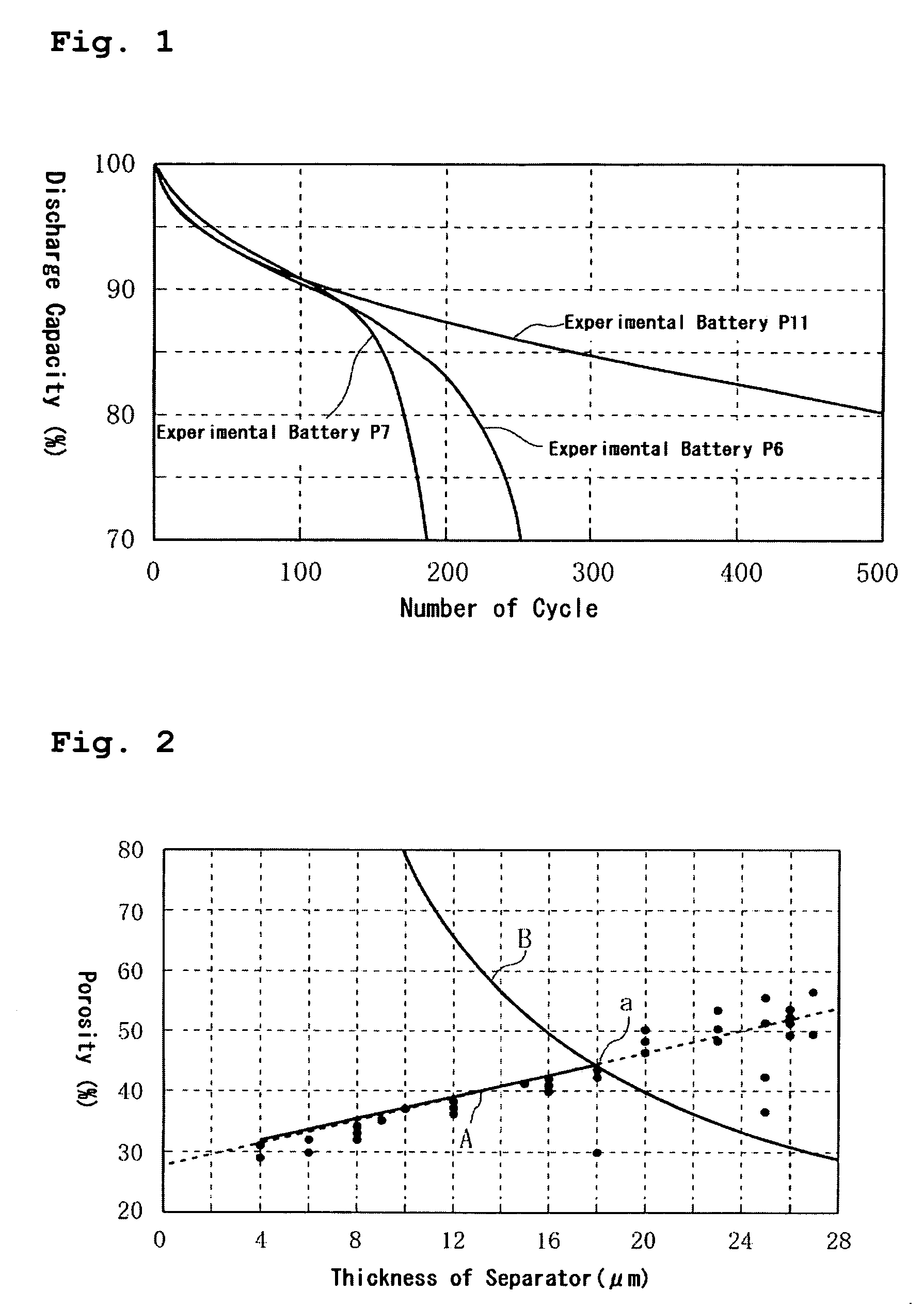
[0068] Experiment 1 examines the relationship between the physical properties (electrolyte accommodating rate) of the separator and cycle life. Specifically, Experimental Batteries P1 to P16 were charged and discharged for 500 cycles under the following charge-discharge conditions (temperature: 25° C.) to examine the cycle life (about whether an electrolyte dry-out occurred and an approximate number of cycles at which cycle life degradation occurred due to the electrolyte dry-out) of each of the batteries. The results are collectively shown in Tables 1 to 3. As for Experimental Batteries P6, P7, and P11, the relationship between number of cycles and discharge capacity was also examined. The results are shown in FIG. 1.

Charge-Discharge Conditions

[0069] Charge Conditions

[0070] Each of the batteries was charged at a constant current of 1C (850 mA) to 4.2 V and charged at a constant voltage 4.2 V to a current of C / 20 (42.5 mA).

[0071] Discharge Test

[0072] Each of the batteries was ...

experiment 2

[0082] Experiment 2 examined the conditions necessary to pass the thermal test for batteries specified by the UL standard. Specifically, in the measurement of thermal contraction of a separator as described in the following, it is desirable that a separator shows a thermal contraction of 20% or lower after the separator has been kept at 120° C. for 10 minutes.

Measurement of Separator Thermal Contraction

[0083] Each of test pieces of separators (5 cm×2 cm) was placed between slide glasses, and both ends of the glasses were fixed with clips. The test pieces were retained for 10 minutes at various temperatures to obtain percentage of shrinkage.

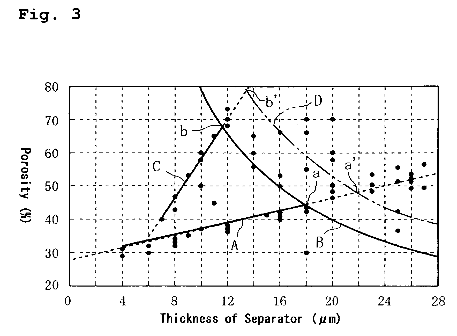
[0084] The results indicated that when the thickness of the separator exceeded 18 μm, the anti-thermal contraction performance can be ensured corresponding to the necessary strength (corresponding to the later-described thermal test) because of the thickness, so the porosity can be relatively freely set even if the separator is formed of a pol...


PUM

PropertyMeasurementUnit
Temperatureaaaaaaaaaa
Thicknessaaaaaaaaaa
Thicknessaaaaaaaaaa

Abstract

A battery separator and a non-aqueous electrolyte battery using the separator are provided that are capable of achieving thickness reduction while fulfilling an insulating function, an electrolyte retention function, and a shutdown function. A battery separator, to be impregnated with a non-aqueous electrolyte and interposed between a positive electrode and a negative electrode, includes a structure of a plurality of layered microporous films, at least one of which includes a reinforcement film made of a polyolefin-based material, and at least one of the rest of which includes a heat-resistance film made of a material having a melting point of 200° C. or higher. The value obtained by multiplying separator thickness (μm) by separator porosity (%) is restricted to 792 μm·% or greater.

Description

BACKGROUND OF THE INVENTION [0001] 1. Field of the Invention [0002] The present invention relates to an improvement in non-aqueous electrolyte secondary batteries, such as lithium-ion batteries and polymer batteries, and more particularly relates to a battery separator that has excellent heat resistance and is capable of obtaining good cycle performance even with high energy density batteries. [0003] 2. Description of Related Art [0004] Rapid advancements in size and weight reductions of mobile information terminals such as mobile telephones, notebook computers, and PDAs in recent years have created a demand for higher capacity batteries as driving power sources for such devices. With their high energy density and high capacity, non-aqueous electrolyte batteries that perform charge and discharge by transferring lithium ions between the positive and negative electrodes are widely utilized as the driving power sources for such mobile information terminals as mentioned above. [0005] As...

Claims


Application Information

Patent Timeline
IPC IPC(8): C08J5/22C08J9/00H01M4/02H01M4/36H01M10/05H01M10/0525H01M50/414H01M50/417H01M50/423H01M50/449H01M50/457H01M50/489H01M50/491
CPCH01M2/1653H01M2/1686Y02T10/7011Y02E60/122H01M10/0525Y02E60/10H01M50/449H01M50/417H01M50/457H01M50/414H01M50/491H01M50/489H01M50/423H01M50/46H01M50/463H01M4/131H01M4/525H01M4/133H01M4/587Y02T10/70
Inventor IMACHI, NAOKIYOSHIMURA, SEIJI
Owner SANYO ELECTRIC CO LTD
Why Eureka
Try Eureka