Devices and methods for minimally invasive treatment of degenerated spinal discs

a technology of spinal discs and devices, applied in the direction of spinal implants, joint implants, prostheses, etc., can solve the problems of debilitating back, leg and neck pain, added many more billions of cost annually, and inability to use intra-discal therapy, etc., to achieve the effect of preserving the mobility of the spin

Inactive Publication Date: 2005-10-06
TRIMEDYNE
View PDF30 Cites 341 Cited by
  • Summary
  • Abstract
  • Description
  • Claims
  • Application Information

AI Technical Summary

Benefits of technology

[0047] While two or more spinal stabilization devices can be inserted into the disc, preferably only one spinal stabilization device is inserted, creating single pivot points between the device and the vertebra above and below the device. This takes the pressure off the degenerated disc, preserves the spine's mobil...

Problems solved by technology

Spinal discs which have degenerated due to disease, injury, deformity or old age (dehydration) cause severe, debilitating back, leg and neck pain.
Doctors' office visits, pain killers, steroids, traction and, most importantly, absences from work add many more billions of cost annually.
However, when a portion of the nucleus pulposa has been expelled through a rupture in the annulus of a lumbar disc and is pressing against the nerves in the spine, an intra-discal therapy cannot be used.
However, removing bone from the vertebra to accommodate the larger cage causes bleeding and can weaken the vertebra and result in fractures, with significant adverse results.
Immobilizing a portion of the spine often causes damage to occur over time to the discs above and below the immobilized vertebra, which frequently requires one or more subsequent surgical procedures.
Approximately 400,000 of such spinal fusion surgeries are performed each year in the United States at a cost of about $60,000 each,...

Method used


Image

  • Devices and methods for minimally invasive treatment of degenerated spinal discs
  • Devices and methods for minimally invasive treatment of degenerated spinal discs
  • Devices and methods for minimally invasive treatment of degenerated spinal discs

Examples


first embodiment

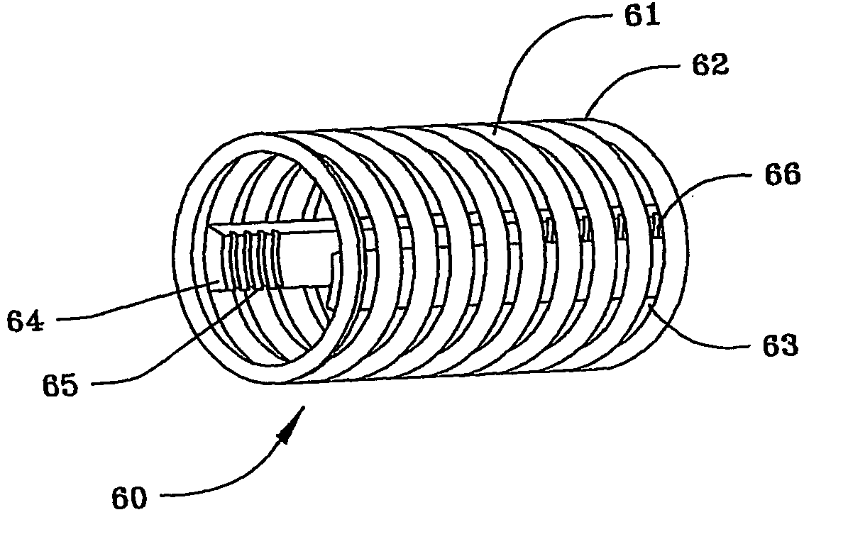
[0103]FIG. 5(a) illustrates a cage 60 of the spinal stabilization device of the present invention. Cage 60 comprises a helical metal coil 61, which may be made of stainless steel or other metal, but is preferably made of titanium or a nickel-titanium alloy. Alternatively, cage 60 can also be made of high density polyethylene or a carbon wire reinforced, strong resilient plastic. Coil 61 can be formed from a metal ribbon, whose exterior edges 62 are beveled into a sharp point and function as threads, as shown, or can be formed from a metal ribbon, wire or rod of any other desired cross section, with at least small spaces 63 between each of the individual coils 61 of cage 60.

[0104] Two or more longitudinal bars 64 are attached by crimping, welding or other means known in the art to the interior surface of coils 61. Bars 64 are positioned opposite each other in a generally co-planar relationship and have helical threads 65 and 66 on at least a portion of the interior of their distal an...

embodiment 140

[0136] As seen in FIG. 13(a), another stabilization device embodiment 140 consists of distal end nose piece or head 141, proximal end piece or plate 142 and outer and inner slats 143 and 144, respectively, which are made of a superelastic, shaped memory metal, such as nitinol. Outer slats 143 and inner slats 144 are attached to distal and proximal end pieces 141 and 142, respectively, by screws, pins, crimping, welding or any other means known in the art. Outer slats 143 contain points or spikes 145 on their outer surface, which function as described above. The plate 142 is similar in structure to the plate 132 which, in turn, is similar in structure to the plate 80. The head 141 is similar to the head 131. The inner slats 144 extend between the radial proximal end faces of the pieces 141 and 142 respectively while the outer slats 143 define a bird-like cage, surround the slats 143, and extend between the outer circumferential distal end surfaces of the pieces 141 and 142 respective...

embodiment 160

[0139] As illustrated in FIG. 15, yet another spinal stabilization device embodiment 160 consists of distal end nose piece or head 161 and proximal end piece or plate 162 similar in structure to the head 70 and plate 80, respectively. The flat metal sheet 150 shown in FIG. 14 has been formed into a tube 163. Helical threads 164 have been formed on the interior surface of the tube 163 adjacent the proximal and distal ends thereof to cooperate and receive threads 165 and 166 formed about the exterior of end pieces 161 and 162 respectively in a manner similar to that described in connection with the FIG. 9 embodiment. Stabilization device 160, when heated above its transition temperature, can expand as described above into the shapes shown in FIGS. 12(b) and 13(b) or any other desired shape. Points or spikes 153 on the exterior of device 160 function as aforesaid.

[0140] As shown in FIG. 16, two separate, flat sheets of superelastic, shape-memory metal 150, such as nitinol, with cut out...


PUM

PropertyMeasurementUnit
Temperatureaaaaaaaaaa
Diameteraaaaaaaaaa
Shape memory effectaaaaaaaaaa

Abstract

Spinal stabilization devices and their methods of insertion and use to treat degenerated lumbar, thoracic or cervical spinal discs in minimally invasive, outpatient procedures are described. In one embodiment, the spinal stabilization device is an expandable cage made of a coil or perforated cylindrical tube with a bulbous or bullet-shaped distal end and a flat or rounded proximal end. In a preferred embodiment, the spinal stabilization device is mechanically expanded to a larger diameter or is made of a superelastic nickel-titanium alloy which is thermally programmed to expand to a relatively larger diameter when a pre-determined transition temperature below body temperature is reached. To treat a degenerated disc, a guide wire is inserted into the disc and an endoscope is inserted through a posterolateral puncture in the back and advanced up to the facet of the spine. Mechanical tools or laser energy, under endoscopic visualization, are used to remove or vaporize a portion of the facet bone, creating an opening into the foraminal space in the spine for insertion of an endoscope, which enables the disc, vertebra and nerves to be seen. The passageway is expanded, mechanical tools or laser of RF energy are used to make a tunnel into the disc, and a delivery cannula is inserted up to the opening of the tunnel. An insertion tool is used to insert one or more spinal stabilization devices into the tunnel in the disc, preserving the mobility of the spine, while maintaining the proper space between the vertebra. Laser or radio frequency (RF) energy is used to coagulate bleeding, vaporize or remove debris and shrink the annulus of the disc to close, at least partially, the tunnel made in the disc.

Description

FIELD OF THE INVENTION [0001] The present invention relates to devices and methods for the treatment of degenerated spinal discs. BACKGROUND OF THE INVENTION [0002] Spinal discs which have degenerated due to disease, injury, deformity or old age (dehydration) cause severe, debilitating back, leg and neck pain. The surgical treatment of degenerated spinal discs in the United States costs about $24 billion each year. Doctors' office visits, pain killers, steroids, traction and, most importantly, absences from work add many more billions of cost annually. [0003] Lower back pain, which often radiates into the legs, affects an estimated 15 million people in the United States and is the principal reason for absences from work. Lower back pain arises from several conditions, the most common causes being a herniated disc, in which the annulus fibrosis or fibrous exterior of the disc has bulged outward and is pressing against the nerves in the spine, a ruptured disc, whose jelly-like nucleus...

Claims


Application Information

Patent Timeline
IPC IPC(8): A61BA61F2/00A61F2/28A61F2/30A61F2/44A61F2/46
CPCA61F2/30744A61F2310/00796A61F2/446A61F2/4611A61F2002/2835A61F2002/3008A61F2002/30092A61F2002/30093A61F2002/30112A61F2002/30205A61F2002/30235A61F2002/3024A61F2002/30253A61F2002/30289A61F2002/30331A61F2002/30405A61F2002/30448A61F2002/30451A61F2002/30507A61F2002/30579A61F2002/30784A61F2002/30841A61F2002/3085A61F2002/30881A61F2002/30971A61F2002/448A61F2002/4627A61F2002/464A61F2210/0014A61F2210/0019A61F2220/0025A61F2220/0033A61F2220/005A61F2220/0058A61F2230/0004A61F2230/0067A61F2230/0069A61F2230/0076A61F2230/0091A61F2250/0098A61F2310/00023A61F2310/00179A61F2310/00365A61F2/30965A61F2/4637
Inventor RICHLEY, RICHARDLOEB, MARVIN P.
Owner TRIMEDYNE
Why Eureka
Try Eureka