Photopic detector system and filter therefor

a detector system and detector technology, applied in the field of detector systems having filters, can solve the problems of inability to meet the needs of many users, easy to damage the filter body, and the phosphate glass is easy to be damaged, etc., and achieve the effect of low transmission

Inactive Publication Date: 2005-10-13
3M INNOVATIVE PROPERTIES CO
View PDF60 Cites 41 Cited by
  • Summary
  • Abstract
  • Description
  • Claims
  • Application Information

AI Technical Summary

Benefits of technology

[0010] The present application discloses detector systems in which a filter positioned in front of a detector selectively transmits light in such a way that the combined filter / detector system closely matches a human eye response. The filter comprises an interference element and an absorptive element. The absorptive element is preferably a polymeric film with one or more specially tailored pigments or other colorants dispersed therein. The interference element is also preferably polymeric, in some embodiments being a coextruded polymer multilayer film The interference element at normal incidence provides high average transmission (at least about 50%, and more preferably at least about 70%) in the visible region, and low transmission (less than about 5%, more preferably less than about 2% or 1 %) throughout a reflection band that extends into the near infrared region. The reflection band of the interference element extends far enough into the near infrared to ensure negligible sensitivity of the detector system to near infrared light. The absorptive element has one or more selected colorants that provide a non-uniform transmission in the visible, preferably having a bell-shaped characteristic suitable to provide the detector system with a near-human eye response in the visible portion of the spectrum when combined with the interference element.
[0011] The filter can be tailored for use with semiconductor photodiodes such as silicon photodiodes. A variety of filter configurations are disclosed, including an absorptive film that is applied to a polymeric interference film, or applied to the detector surface. The absorptive element can also be adhered to the interference element by a suitable adhesive layer, or incorporated into one or more individual layers of the interference element. In some embodiments, the filter can extend across a first aperture of a filter assembly, and the filter assembly can include a second aperture adapted to receive a detector assembly. This modular design has certain advantages relative to a system in which the filter elements are all applied directly to the detector surface. The system can include additional optical elements such as a light scattering layer to reduce angular dependency.

Problems solved by technology

Such detectors, however, have characteristics that make them less than ideal for many uses.
One drawback to these systems is the vulnerability of the phosphate glass to moisture.
Another is the inconvenience and / or difficulty in processing the glass in molding, cutting, and polishing operations, as well as the relatively large specific gravity of the glass.
Glass filters also tend to be quite thick and heavy, which is not desirable for many applications.
The phosphoric acid-group causes the polymer to have poor weather resistance.
As a result, if such an optical filter is exposed to high temperature and high humidity, problems relating to whitening (turbidity) and loss of transparency (opacification) begin to develop.
Such filters unfortunately have poor absorption of light in the near infrared region and the ultraviolet region.

Method used


Image

  • Photopic detector system and filter therefor
  • Photopic detector system and filter therefor
  • Photopic detector system and filter therefor

Examples


example 1

[0071] Mixed ink composition GY1 was coated onto PET base film (Teijin Co.) using a mayerbar, and organic solvent was evaporated in an oven at 80° C. After drying, a PET film having a 1.7 μm thick green / yellow pigment layer was obtained. This film was further maintained in the oven at 70° C. for 24 hours to promote crosslinking reaction. The green / yellow absorptive film had chromaticity values x=0.368, y=0.532. After adhering the absorptive film to the interference film IF1 with acrylic adhesive, the combined film was placed over the detector such that incident light impinged first on the absorptive element and then on the interference element.

example 2

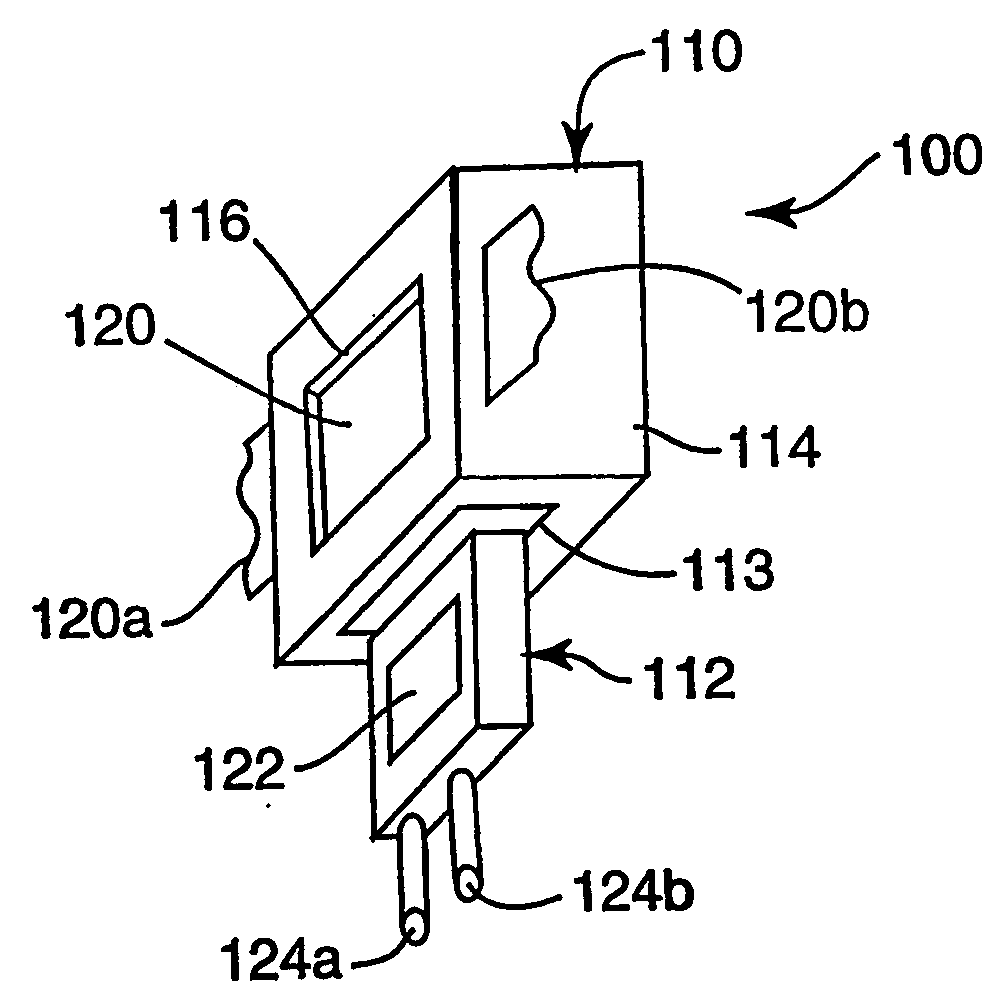
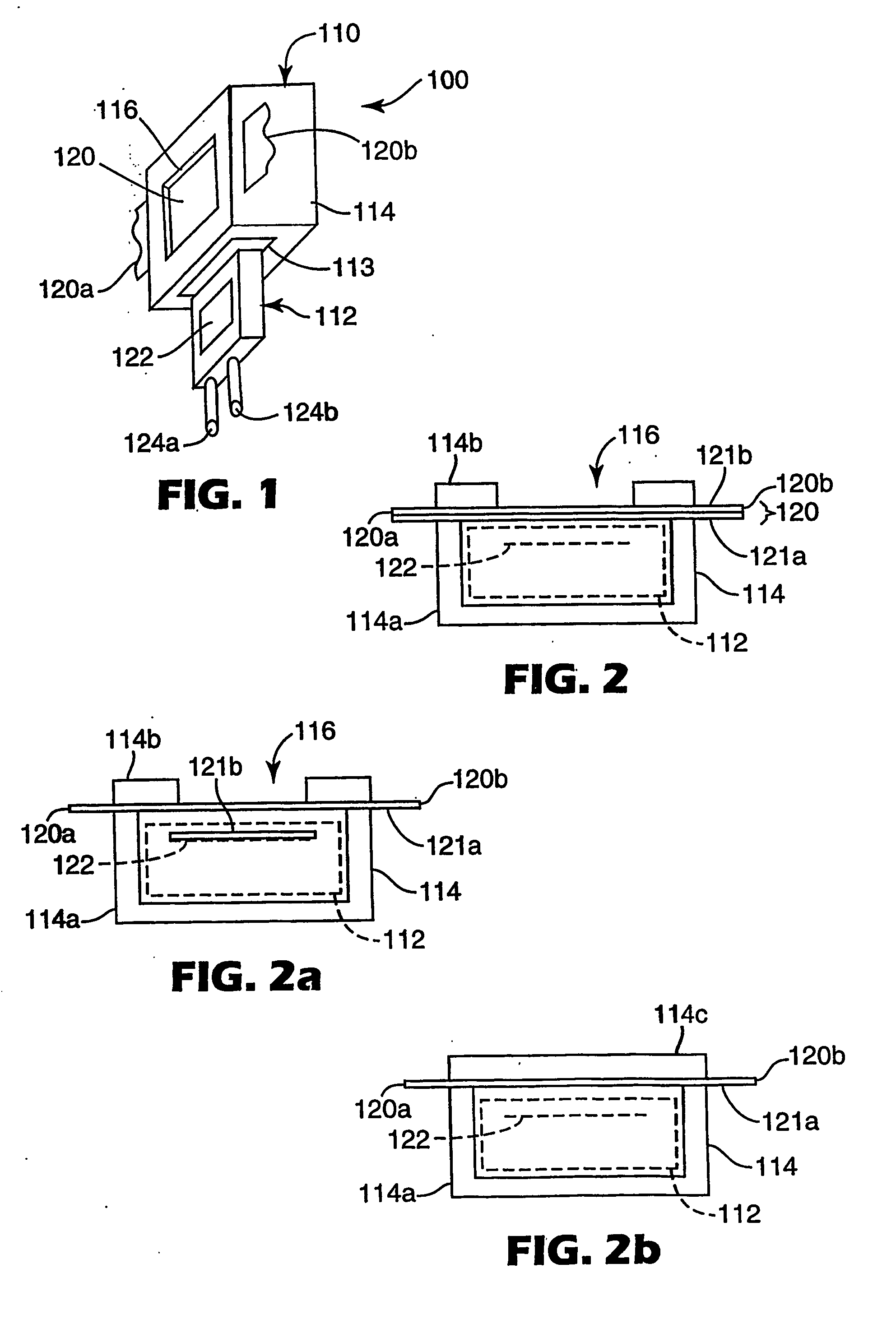
[0072] The interference element IF1 was laser cut to form strips using the procedure described in the U.S. patent application entitled “Method For Subdividing Multilayer Optical Film Cleanly and Rapidly” described above. Before removing the strips from the bottom liner, mixed ink composition GY2 was coated onto interference element IF1 using a spin coater, and organic solvent was evaporated in an oven at 80° C. After drying, a polymer multilayer interference element having a 1.7 μm thick green / yellow absorptive film thereon was obtained. This combination was further maintained in the oven at 70° C. for 24 hours to promote crosslinking reaction. The green / yellow absorptive film had chromaticity values x=0.391, y=0.551. A strip of this combination was removed from the bottom liner, placed in an injection molding machine, and a box-type filter housing (see FIG. 1) was formed around the strip. The resulting filter assembly was placed over the detector such that incident light impinged f...

example 3

[0073] The interference element IF1 was laser cut to form strips using the procedure described in the U.S. patent application entitled “Method For Subdividing Multilayer Optical Film Cleanly and Rapidly” described above. Before removing the strips from the bottom liner, mixed ink composition GY2 was coated onto interference element IF1 using a spin coater, and organic solvent was evaporated in an oven at 80° C. After drying, a polymer multilayer interference element having a 1.7 μm thick green / yellow absorptive film thereon was obtained. This combination was further maintained in the oven at 70° C. for 24 hours to promote crosslinking reaction. The green / yellow absorptive film had chromaticity values x=0.391, y=0.551. A strip of this combination was removed from the bottom liner, placed in an injection molding machine, and a box-type filter housing (see FIG. 1) was formed around the strip. The resulting filter assembly was placed over the detector such that incident light impinged f...


PUM


Abstract

A detector system, filter therefor, and method of making same is disclosed. The filter includes an interference element having a reflection band disposed primarily in the near infrared, and having a high transmission over most of the visible region. The filter also includes an absorptive element that absorbs light non-uniformly over the visible region. The filter when combined with a semiconductor photodiode or other suitable detector yields a detector system whose spectral responsivity closely matches the visual response of the human eye.

Description

CROSS REFERENCE TO RELATED APPLICATIONS [0001] The present application claims priority as a continuation-in-part to U.S. application Ser. No. 10 / 152,546, filed May 21, 2002.FIELD OF THE INVENTION [0002] The present invention relates to detector systems having filters that produce a desired spectral response. More particularly, the present invention relates to detector systems that have a spectral responsivity substantially matched to that of the human eye, and filters therefor. BACKGROUND [0003] Electronic detectors have long been used in photography and related fields to provide a measurement of the brightness of a scene or object. In order for the measurement to at least crudely represent the brightness as perceived by the human eye, detectors such as the cadmium sulfide photocell have been used. These detectors have spectral responsivities that peak in the visible region and at least roughly approximate the responsivity of the human eye. Such detectors, however, have characterist...

Claims


Application Information

Patent Timeline
Patent Type & Authority Applications(United States)
IPC IPC(8): G01J1/00G01J3/51G01J1/04G01J1/42G01J3/50G02B5/22G02B5/28
CPCG01J1/42G02B5/22G01J3/51
Inventor HARADA, TAKASHIMIZUNO, KAZUHIKOWHEATLEY, JOHN A.NEVITT, TIMOTHY J.OUDERKIRK, ANDREW J.
Owner 3M INNOVATIVE PROPERTIES CO
Why Eureka
Try Eureka