
Fixed abrasive tools and associated methods

a technology of abrasive tools and associated methods, which is applied in the field of polishing tools, can solve the problems of large volume of abrasive slurry waste, clogging of pores or fibers of cmp pads, and sensitive control parameters, and achieves the effect of adequate material removal rate and facilitates debris removal

Inactive Publication Date: 2005-10-13
SUNG CHIEN MIN
View PDF43 Cites 184 Cited by
  • Summary
  • Abstract
  • Description
  • Claims
  • Application Information

AI Technical Summary

Benefits of technology

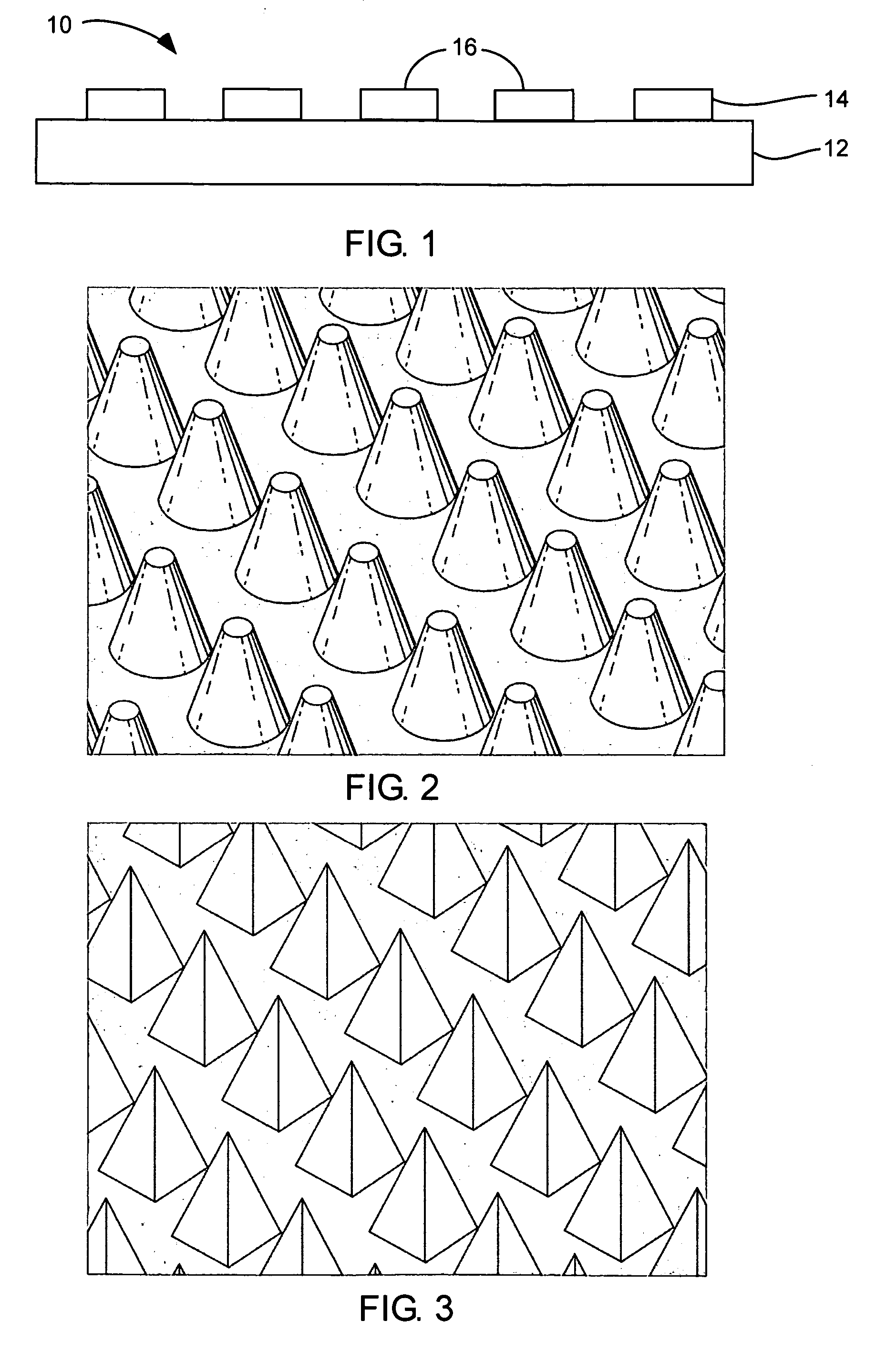
[0009] Nanodiamond particles used in the present invention typically can have a particle size from about 1 nm to about 50 nm, and preferably about 2 nm to about 10 nm. In one specific aspect, the nanodiamond particles can include a carbonaceous coating. This carbonaceous coating can provide beneficial lubrication effects, without substantially reducing removal of material from a workpiece. Most often, the carbonaceous coating includes a thin layer of non-diamond carbon, e.g., fullerenes, surrounding each nanodiamond particle.
[0014] Typically, a polishing liquid can be introduced to the surface during the step of polishing in order to facilitate removal of debris. In one alternative aspect, the polishing liquid can be a moderate solvent for the organic matrix. In this way, the organic matrix can be slowly dissolved as exposed nanodiamond particles become worn in order to allow these particles to become dislodged and removed. As the organic matrix dissolves, new unused nanodiamond particles can be constantly exposed to maintain adequate material removal rates from the workpiece with an extended useful life. In yet another detailed aspect, the polished surface can have a surface roughness (Ra) less than about 2 nm, and preferably about 2 Å to about 10 Å.
[0015] The fixed abrasive tools of the present invention can be used to polish any number of workpieces. However, the present invention can be particularly suitable for polishing expensive workpieces such as silicon wafers, integrated circuitry, gemstones, and hard drive platters.

Problems solved by technology

Such polishing processes can be effective, but also suffer from sensitive control parameters and large volumes of abrasive slurry waste.
During the course of polishing, the pores or fibers of the CMP pad become clogged with debris removed from the workpiece or the pad, as well as abrasive particles from the slurry trapped along with the debris.
Moreover, the pad fibers can be subjected to high temperatures during contact with the wafer surface.
As a result, irreversible changes can occur due to partial melting of the pad.
Further, accumulation of debris and abrasive particles can cause glazing or hardening of the pad.
This accumulation within the pad fibers reduces its capacity to store slurry and support abrasives for effectively removing material from the workpiece.
While pads utilizing a slurry have been effective in achieving a wide variety of polishing results, such pads suffer various drawbacks such as abrasive particle aggregation.
Additionally, because the abrasive particles are not physically attached to the pad, but rather are free moving, it is difficult to increase the rate of material removal from a workpiece by simply increasing the rotation speed of the pad.
Unfortunately, most fixed abrasive polishing pads result in excessive scratching of polished surfaces.
Typical abrasives used in these fixed abrasive pads are either too large and / or contain excessive sharp edges which do not allow for ultra-fine polishing and leave excessive scratches on the workpiece.
This excessive scratching is generally unacceptable for applications where a high degree of smoothness is required.

Method used


Image

  • Fixed abrasive tools and associated methods
  • Fixed abrasive tools and associated methods
  • Fixed abrasive tools and associated methods

Examples


Embodiment Construction

[0028] Before the present invention is disclosed and described, it is to be understood that this invention is not limited to the particular structures, process steps, or materials disclosed herein, but is extended to equivalents thereof as would be recognized by those ordinarily skilled in the relevant arts. It should also be understood that terminology employed herein is used for the purpose of describing particular embodiments only and is not intended to be limiting.

[0029] It must be noted that, as used in this specification and the appended claims, the singular forms “a,” and “the” include plural referents unless the context clearly dictates otherwise. Thus, for example, reference to “a nanodiamond particle” includes one or more of such particles, reference to “a projection” includes reference to one or more of such structures, and reference to “a printing process” includes reference to one or more of such processes.

Definitions

[0030] In describing and claiming the present inve...


PUM

PropertyMeasurementUnit
Pressureaaaaaaaaaa
Pressureaaaaaaaaaa
Particle sizeaaaaaaaaaa

Abstract

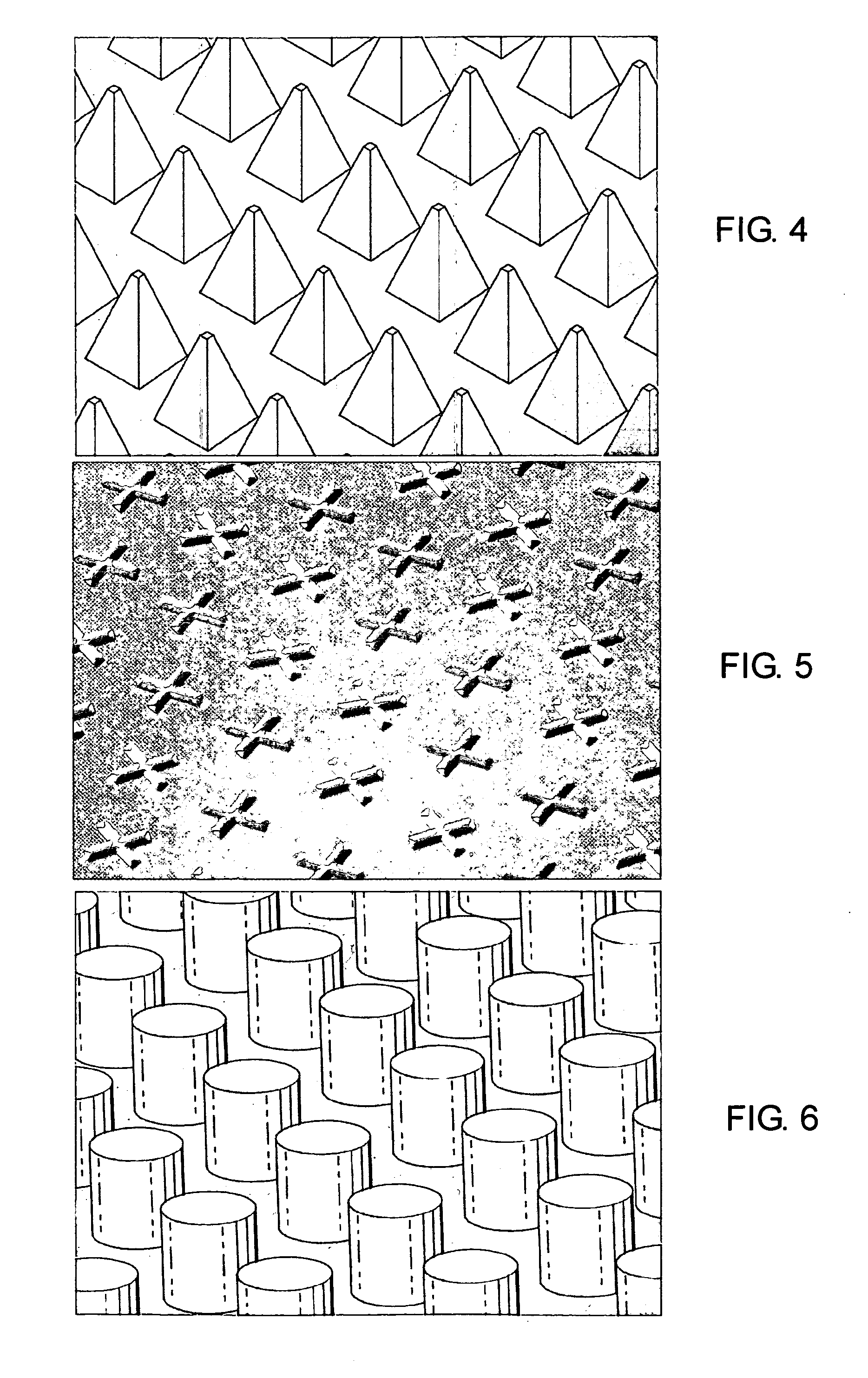
A fixed abrasive tool incorporating nanodiamond particles is described and disclosed. A fixed abrasive tool can include a polishing layer on a substrate. The polishing layer can include an organic matrix with nanodiamond particles therein. The polishing layer can be formed in a wide variety of configurations, depending on the specific polishing application. Most often, the polishing layer can include a plurality of projections which can have a wide variety of configurations in order to achieve a particular polishing performance. Nanodiamond particles used in the present invention can have a particle size from about 1 nm to about 50 nm, and preferably about 2 nm to about 10 nm. Optionally, the nanodiamond particles can include a carbonaceous coating. Such fixed abrasive tools can be formed by screen printing of a slurry of nanodiamond particles and an organic binder to form a predetermined three-dimensional pattern. Other methods can also be used to form the disclosed nanodiamond fixed abrasive tools. These fixed abrasive tools are particularly suitable for polishing expensive workpieces such as silicon wafers, integrated circuitry, gemstones, and hard drive platters.

Description

FIELD OF THE INVENTION [0001] The present invention relates to devices and methods for use in connection with polishing various workpieces. More particularly, the present invention relates to polishing tools which incorporate nanodiamond, and accompanying methods for making and design thereof. Accordingly, the present invention involves the fields of chemistry, metallurgy, and materials science. BACKGROUND OF THE INVENTION [0002] In various industrial applications, it is often desirable to polish a workpiece to obtain a quality finish having a low surface roughness. Chemical mechanical planarization (CMP) has become a widely used technique for removing material from a workpiece. In particular, CMP is particularly useful for polishing expensive workpieces including ceramics (e.g., sapphire), silicon (e.g., wafers, semiconductor devices, etc.), GaAs (e.g., diodes), GaN (e.g., LED), glass (e.g., LCD), quartz (e.g., oscillators), gemstones (e.g., diamond, ruby, cubic zirconia, etc.), me...

Claims


Application Information

Patent Timeline
IPC IPC(8): B24B1/00B24D11/00
CPCB24D11/001B24D2203/00
Inventor SUNG, CHIEN-MIN
Owner SUNG CHIEN MIN
Learn More