Manufacturing system for microstructure

Inactive Publication Date: 2005-10-20
MITSUBISHI HEAVY IND LTD
View PDF2 Cites 20 Cited by
  • Summary
  • Abstract
  • Description
  • Claims
  • Application Information

AI Technical Summary

Problems solved by technology

In the above-described lamination molding method, it is a major issue in the future to improve form accuracy of the microstructure and to increase the number of laminations of the thin film members constituting the cross-sectional forms in the direction of lamination at the same time, and a concrete countermeasure technique is demanded.
Moreover, since the above-described laminate molding method is performed in high vacuum, the stage has to deal with high vacuum.
However, these types have the following probl

Method used


Image

  • Manufacturing system for microstructure
  • Manufacturing system for microstructure
  • Manufacturing system for microstructure

Examples


Embodiment Construction

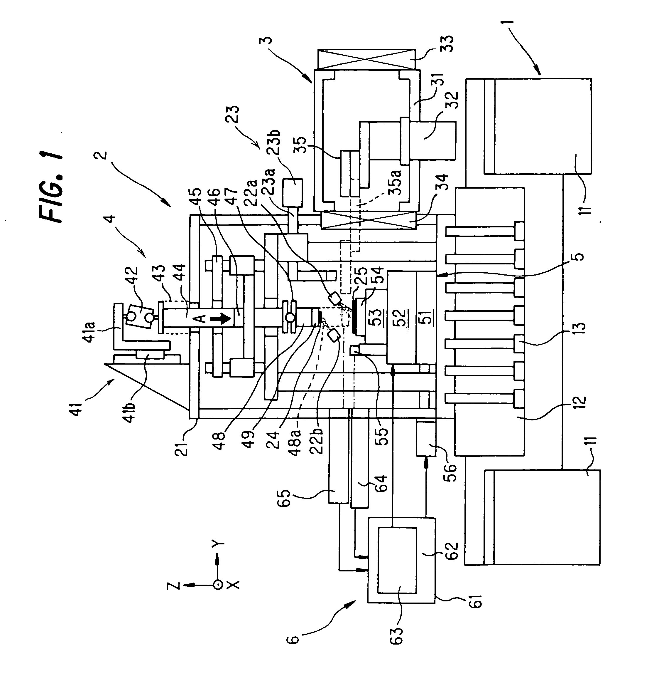
[0053] A manufacturing system for a microstructure according to the present invention is configured to bond and laminate a plurality of thin film members and the like and thereby to manufacture a microstructure, by element of positioning the plurality of thin film members having an arbitrary two-dimensional pattern or three-dimensional pattern, a substrate including formation of a plurality of arbitrary two-dimensional patterns or three-dimensional patterns or the like (a pressure-contacted member) relative to a pressure-contacting target member to be disposed opposite, then performing pressure-contacting and separating, and then repeating these steps.

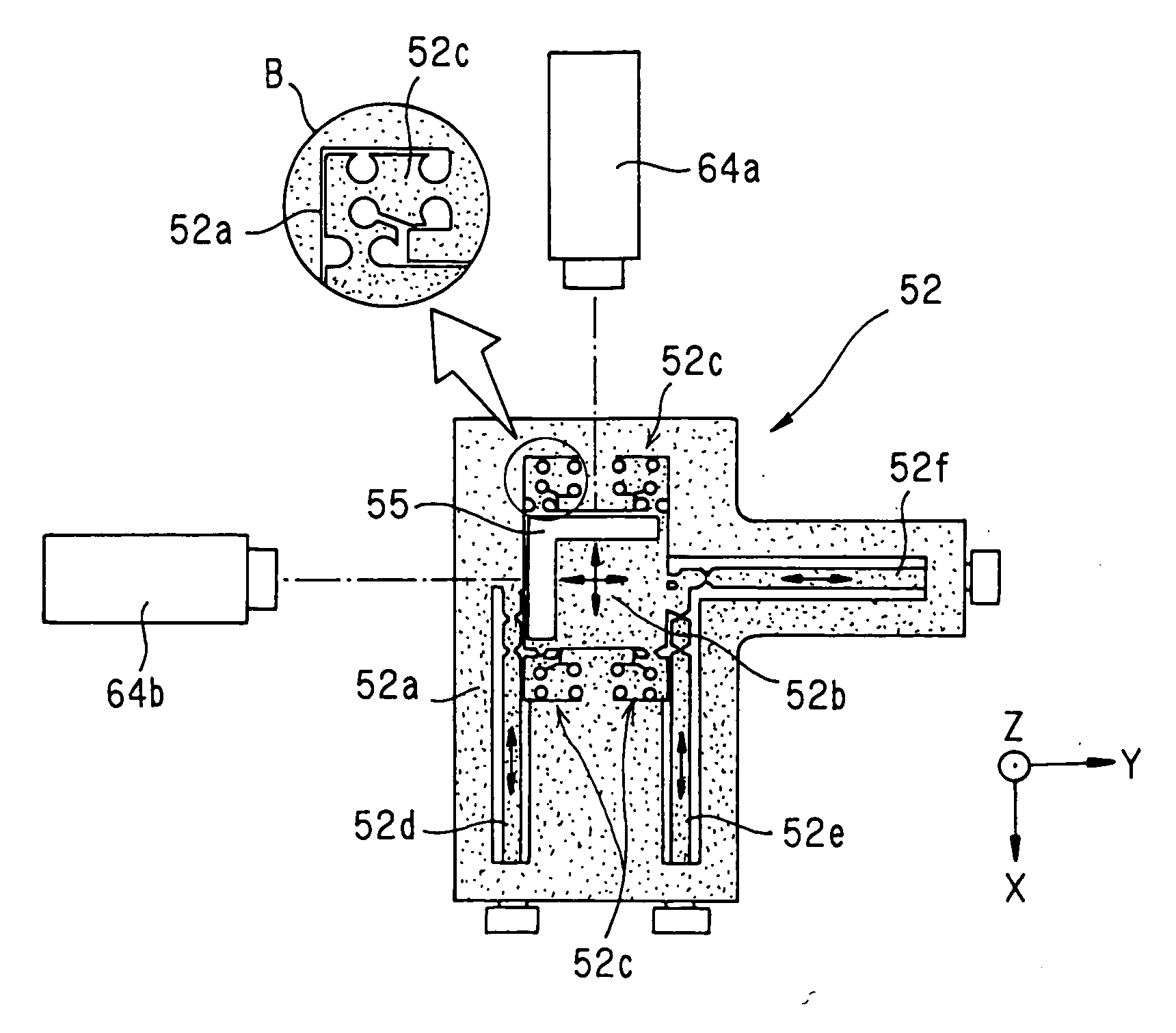
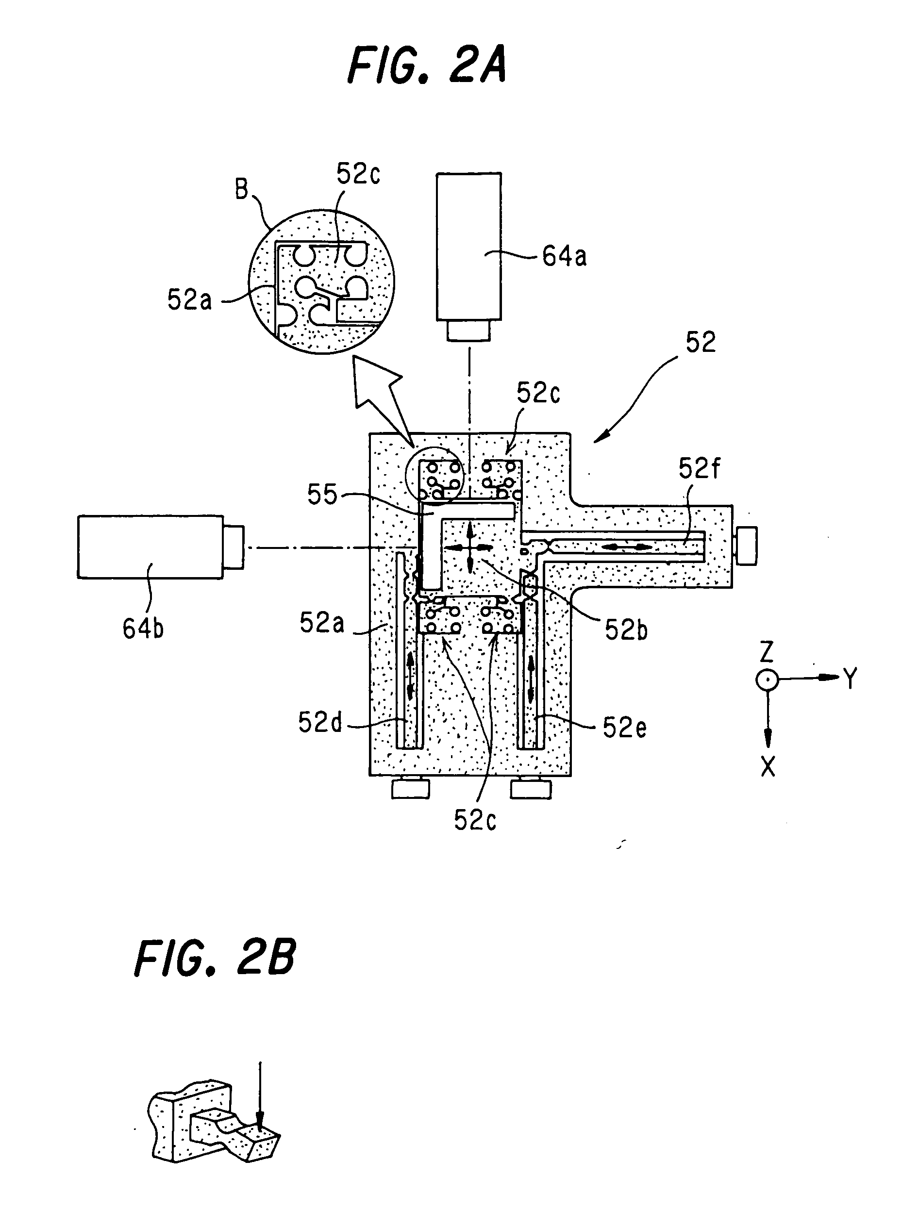
[0054] In the manufacturing system for a microstructure according to the present invention, a stage device is used to obtain a high degree of positioning accuracy, in which, on a large-stroke rough motion stage (a first stage) having predetermined positioning accuracy there is disposed a small-stroke fine motion stage (a second stage)...


PUM

PropertyMeasurementUnit
Forceaaaaaaaaaa
Pressureaaaaaaaaaa
Microstructureaaaaaaaaaa

Abstract

A manufacturing system for a microstructure includes a rough motion stage having predetermined positioning accuracy and a large stroke length, a fine motion stage disposed on the rough motion stage and having higher positioning accuracy than the rough motion stage and a small stroke length, and the like collectively as a stage device disposed in a vacuum container, laser length measuring machines for measuring a distance to a mirror disposed on the fine motion stage, a stage control device for driving the fine motion stage by a result of measurement by the laser length measuring machines, and the like collectively as a stage control unit, and a pressing rod 44 for holding a pressure-contacting target member disposed opposite to a pressure-contacted member held by the stage device and pressure-contacting and separating the members, a pressure-contacting drive mechanism for applying a pressure-contacting force to the pressing rod 44, and the like collectively as a pressure-contacting mechanism unit.

Description

[0001] The entire disclosure of Japanese Patent Application No. 2004-111769 filed on Apr. 6, 2004, including specification, claims, drawings and summary, is incorporated herein by reference in its entirety. BACKGROUND OF THE INVENTION [0002] 1. Field of the Invention [0003] The present invention relates to a manufacturing system for a microstructure to be formed by laminating thin film members. [0004] 2. Description of the Related Art [0005] Along with the growth in fine processing technologies in recent years, numerous manufacturing methods for fabricating microstructures in three-dimensional forms have been developed. Among them, a laminate molding method of performing transfer and lamination onto a substrate by use of a room temperature contacting method is drawing attention. This is the method of forming respective cross-sectional forms in a lamination direction of a microstructure as thin film members on a substrate in a lump by use of a semiconductor manufacturing process, of ...

Claims


Application Information

Patent Timeline
IPC IPC(8): B29C65/00B81C3/00B81C99/00
CPCB29C65/002B29C65/006Y10T74/20354B29C67/0096B29C66/022B29C66/73161B29K2995/0072B29C66/9672B29C65/7817B29C66/0222B29C66/028B29C64/35B29C66/7352
Inventor TSUNO, TAKESHIGOTO, TAKAYUKITAWARA, SATOSHIKINOUCHI, MASATOASANO, SHINHASEGAWA, OSAMUYAMADA, TAKAYUKITAKAHASHI, MUTSUYA
Owner MITSUBISHI HEAVY IND LTD
Why Eureka
Try Eureka