
Method and apparatus for carbon allotropes synthesis

a carbon allotrope and synthesis technology, applied in the field of carbon allotrope synthesis, can solve the problems of low production rate, low production rate, and insufficient production rate to organize large-scale industrial process to produce fullerenes in large quantities and low price, and achieve the effect of easy and inexpensiv

Inactive Publication Date: 2005-10-20
DUBROVSKY ROMAN +1
View PDF14 Cites 37 Cited by
  • Summary
  • Abstract
  • Description
  • Claims
  • Application Information

AI Technical Summary

Benefits of technology

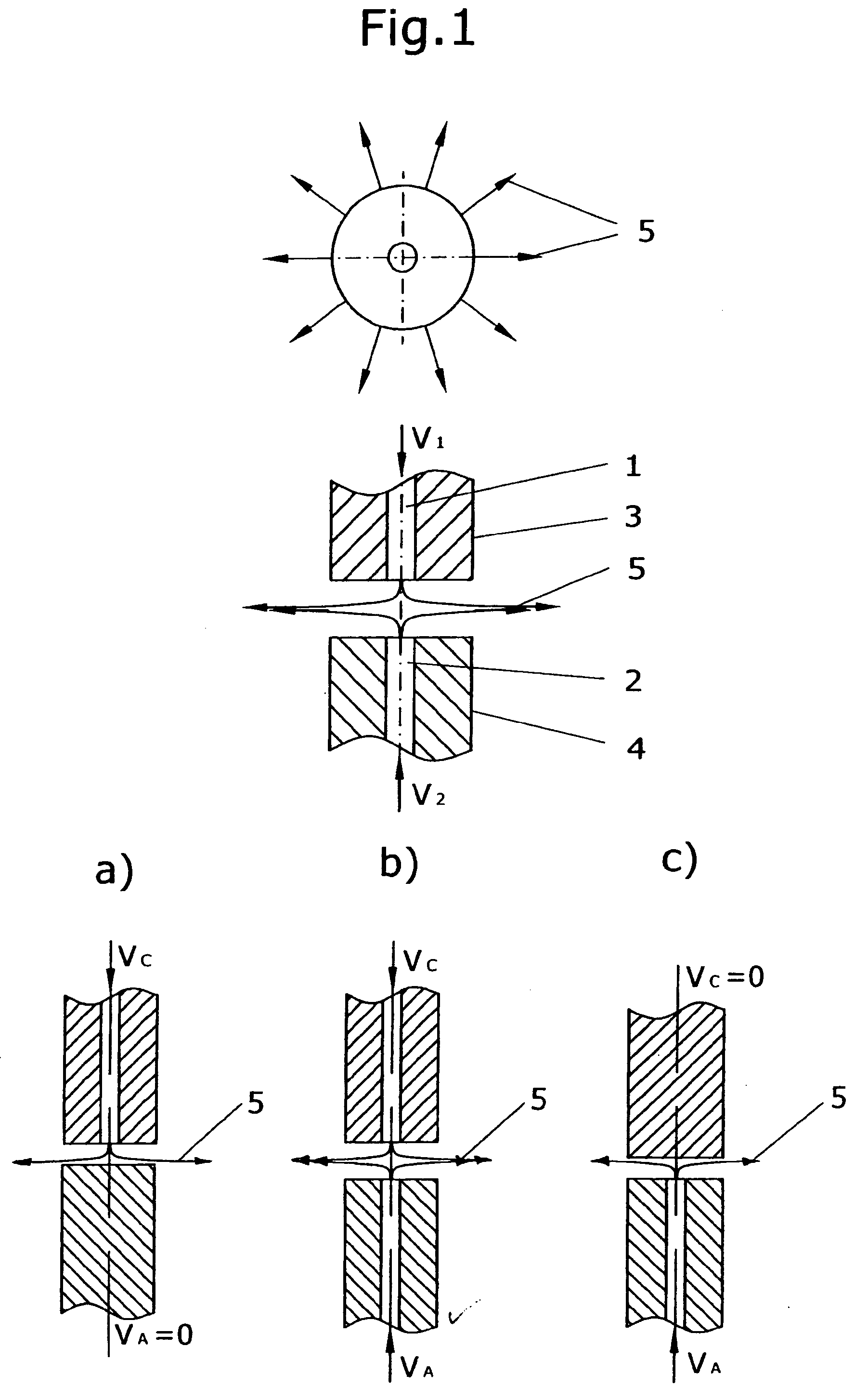
[0014] In addition to the apparatus of the present invention five preferred embodiments of electrode design are presented. Three preferred embodiments are to be employed as non-consumable cathodes in DC arc plasma process and serve as buffer gas flow distributors to eliminate the problem of cathode deposit. They include: multiple-channel electrode with branched channels, multiple-channel electrode with additional annular channel and multiple-channel electrode with parallel channels having special outlets. Another two preferred embodiments disclose the electrode designs, which are to be employed as consumable anodes in DC arc plasma process or as both electrodes in AC arc plasma process. They offer an easy and inexpensive way of creating a gas-tight longitudinal inner gas channels in an expendable electrode and allows to introduce metallic catalyst in the form of metal wires or strips used in carbon nanotubes synthesis. They include assemblies of graphite rods of different geometry with or without metal catalyst inserts.

Problems solved by technology

The method was very simple but production rates were too small, about 1 gram / hour.
All these and many other methods represent significant departure from electric arc plasma method but their production rates were still not enough to organize large-scale industrial process to produce fullerenes in large quantities and at low price.
Though all prior methods exhibit limited applicability, electric arc discharge between graphite electrodes was historically the most common method for the purposes of macroscopic production of carbon allotropes such as fullerenes and nanotubes.
Applying higher electrical currents will increase the total mass of vaporized graphite but dramatically will reduce fullerene yield.
Cathode deposit growth, strong UV radiation, insufficient quenching rates at high currents and small diameters of electrodes were the four main limitations of the electric arc plasma method.
Cathode deposit is a troublesome phenomenon in electric arc plasma process.
Strong UV radiation is another serious limitation for carbon allotropes productivity in the electric arc plasma method.
Usage of higher currents creates larger hot plasma zone, requires higher quenching rates and, as a rule, decreasing the fullerene yield.
Such thin electrodes are fragile and fast consumable.
They are also very expensive to manufacture.
Though carbon allotrope yields were increased, the overall productivity remained low.
Furthermore, the problems of cathode deposit growth and usage of small electrode diameters were still keeping the electric arc plasma method far away from being utilized for production of fullerenes and nanotubes in bulk.

Method used


Image

  • Method and apparatus for carbon allotropes synthesis
  • Method and apparatus for carbon allotropes synthesis
  • Method and apparatus for carbon allotropes synthesis

Examples


example 1

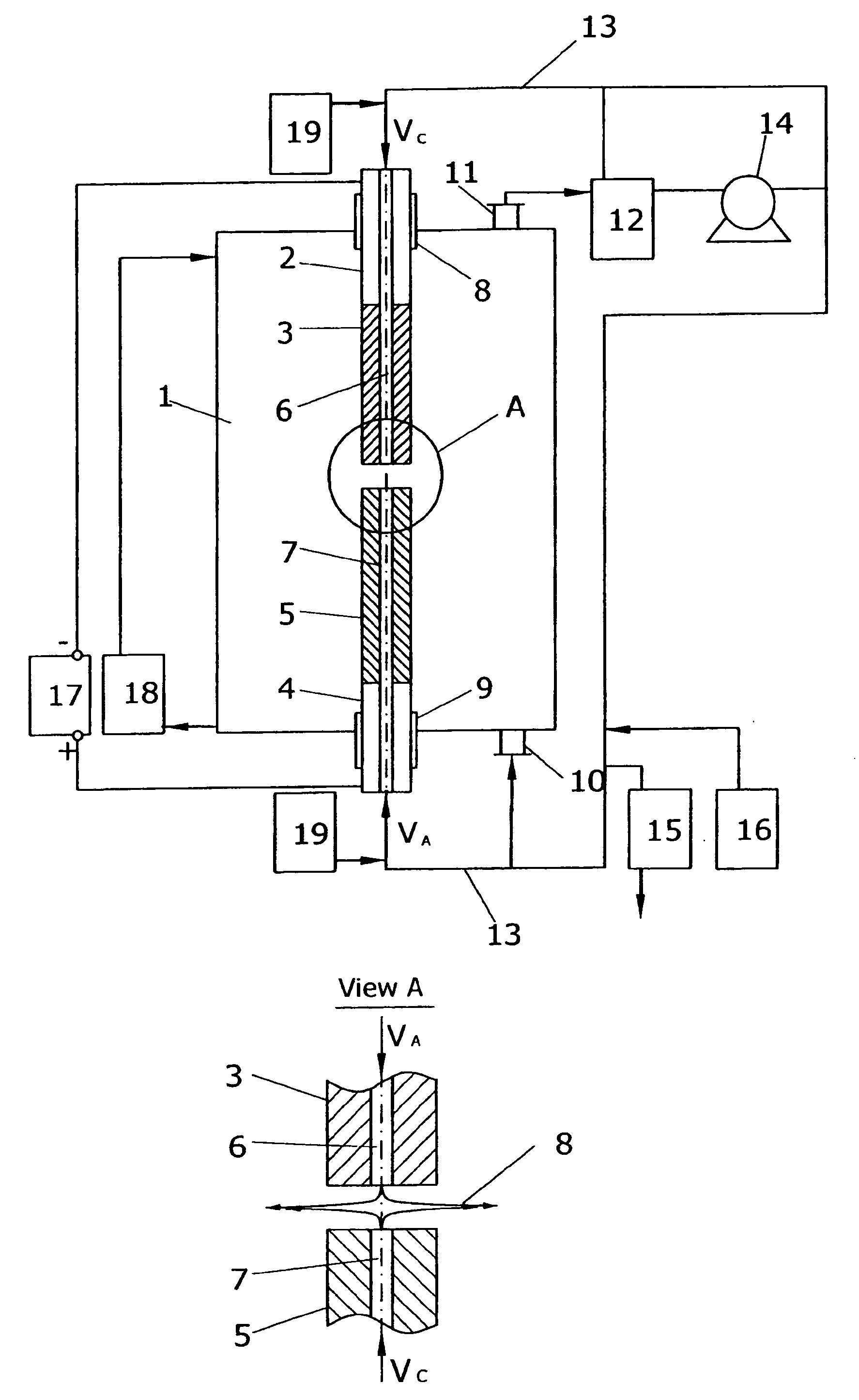
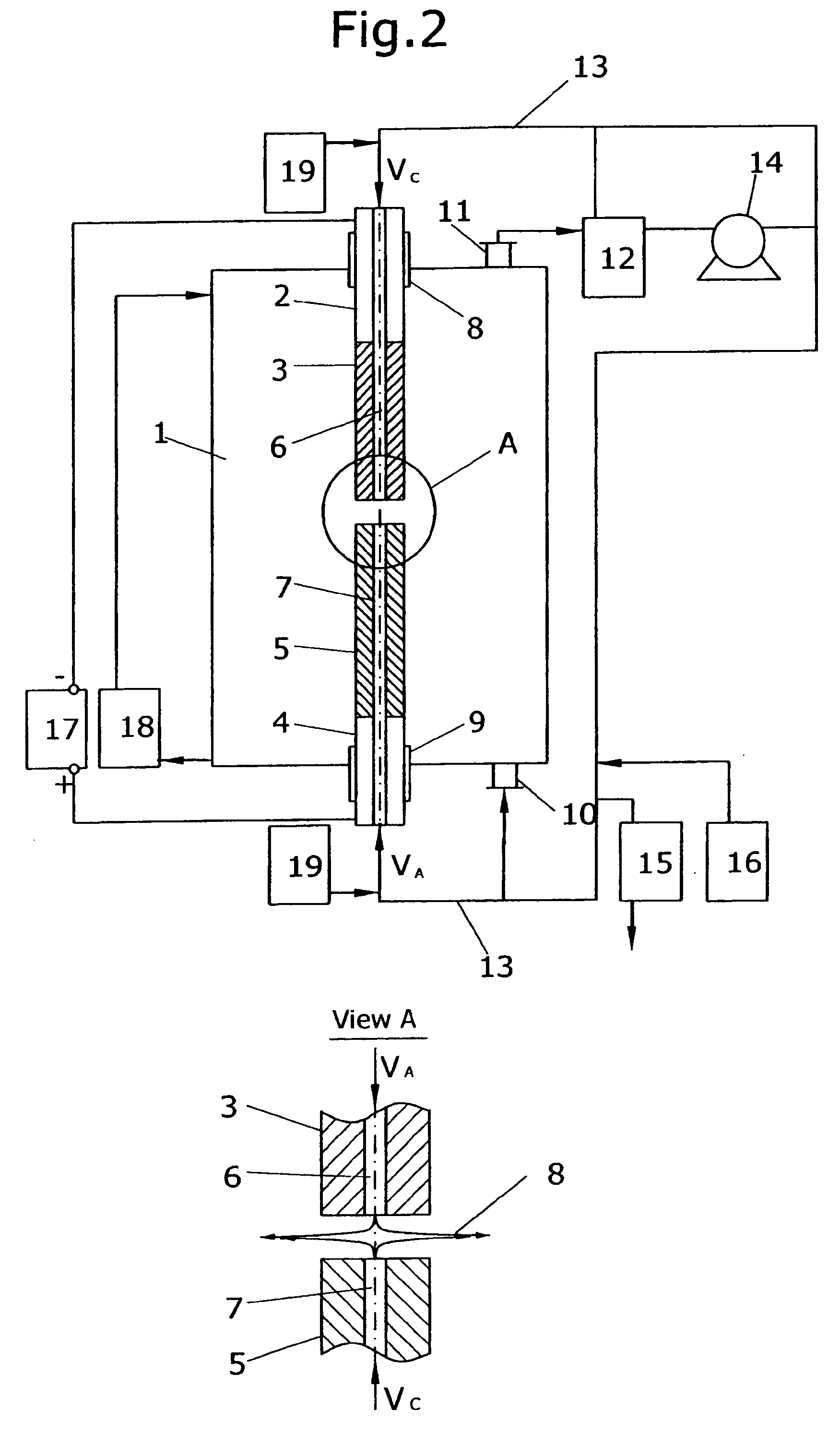
[0055] Process of fullerene synthesis was accomplished using the apparatus shown on FIG. 2. Reaction vessel with internal diameter 235 mm and length 600 mm was used. Both cathode and anode were made out of 580 Grade Graphite purchased by “Carbide / Graphite Group” with diameter 13 mm. Cathode had single central inner gas channel 1.5 mm in diameter. Initial masses of cathode and anode were measured and electrodes were attached to the corresponding electrode holders. The reaction vessel was assembled and purged by buffer gas according to the procedure described above. Helium of Zero Grade with the flow rate of 7.5 L / min was injected to the hot plasma zone through the single cathode channel, providing radial gas outflow. Reaction vessel pressure was maintaining at the level of 780 Torr.

[0056] Electrical current of 300 A, 29 VDC was applied to the electrode holders. The constant gap of about 5 mm between electrodes was automatically maintained during the process by adjusting of electrode...

example 2

[0058] Example 2 was performed at exactly the same manner as the Example 1. Various levels of radial gas outflow were applied. The results are presented in the Table 1.

TABLE 1AnodeRadialmassCol-gasevap-CathodelectedFullereneFullereneSampleoutflow,orated,deposit,soot,yield,productivity,#L / minggg% massg / hour1052.227.723.11.60.72148.325.222.34.72.13346.516.828.410.66.044.547.113.632.613.99.157.542.77.134.316.111.0

[0059] Table 1 indicates significant positive influence of radial gas outflow on the fullerene yield and fullerene productivity. Radial gas outflows more then 7.5 L / min were tended to blow up the arc. Radial gas outflows below 3 L / min were not enough to move carbon vapor effectively out of the hot plasma zone. In this case central cathode inner gas channel was partly blocked by growing deposit and was blocked completely at the absence of radial gas outflow.

example 3

[0060] Example 3 was performed according to the same procedure as the Example 1 but different process parameters were applied. Multi-channel cathode design was applied (FIG. 3). Cathode with diameter 25 mm had 5 inner gas channels with round outlets 1.5 mm in diameter each. Anode with diameter 18 mm was applied. All process parameters and results are presented in the Table 2.

TABLE 2Process ParametersHelium flow, L / min40Pressure, Torr800Current, A650Voltage, V34Total time, min12ResultsAnode mass evaporated, g196.4Cathode deposit, g6.3Soot collected, g187.7Fullerene yield, % mass8.9Fullerene productivity, g / hour83.5


PUM


Abstract

A method and apparatus for synthesis of fullerenes and nanotubes in large quantities at an economical cost from graphite in electric arc plasma process are presented. Different embodiments of channeled graphite electrodes for both direct current (DC) and alternative current (AC) processes are disclosed. High productivity of the carbon allotropes is achieved by feeding consumable graphitic electrode into hot plasma zone, injecting of feedstock, catalyst and buffer gas flow through the longitudinal inner channel electrodes into the hot plasma zone and creating the radial gas outflow in the gap between electrodes, and following removal of produced carbon and catalytic vapors from the hot plasma zone into an oxygen deprived reaction vessel for quenching and condensing. Deposited after condensation soot containing carbon allotropes is collected and carbon allotropes are recovered by known techniques. The final products of recovering are fullerenes C60, C70 and higher fullerenes or nanotubes.

Description

BACKGROUND OF THE INVENTION [0001] In 1985 Robert F. Curl and Richard E. Smalley from Rice University working together with Harold W. Kroto from University of Sussex reported that a new form of carbon could be made by laser irradiation of graphite electrode to produce soot in an evaporation chamber [H. W. Kroto et. al., “C60 Buckminsterfullerene”, Nature, 318, 162-163 (1985)]. In 1990 W. Kreatchmer and D. Huffman announced that they found more simple way to produce the mixture of C60 & C70 by striking an arc between two graphite electrodes and forming soot from the vaporized carbon [W. Kreatchmer et. al., “Solid C60: A new form of carbon”, Nature, 347, 354-357 (1990)]. The method was very simple but production rates were too small, about 1 gram / hour. [0002] Later on some alternative techniques were introduced like a sputtering method disclosed in the U.S. Pat. No. 5,494,558, where fullerene-containing soot was prepared by bombardment of a carbon target with sufficient amount of posi...

Claims


Application Information

Patent Timeline
IPC IPC(8): B01J19/08C01B31/02
CPCB01J19/088C01B31/0233B01J2219/0815B01J2219/0822B01J2219/083B01J2219/0839B01J2219/0841B01J2219/0869B01J2219/0871B01J2219/0886B01J2219/089B01J2219/0892B01J2219/0898B82Y30/00B82Y40/00C01B31/0213B01J2219/0809C01B32/162C01B32/154
Inventor DUBROVSKY, ROMANBEZMELNITSYN, VALERIY
Owner DUBROVSKY ROMAN
Learn More