
Sample Deposition Method and System

a sample and sample technology, applied in the field of mass analysis, can solve the problems of unmet demand for a rapid and efficient means to prepare and handle large numbers of lc fractions for analysis by ms, wear and breakage, and difficulty in preserving chromatographic resolution, so as to achieve enhanced chromatographic resolution of samples, increase sampling speed, and increase sample throughput

Inactive Publication Date: 2005-10-20
IRM
View PDF30 Cites 40 Cited by
  • Summary
  • Abstract
  • Description
  • Claims
  • Application Information

AI Technical Summary

Benefits of technology

"This patent describes a new system and method for depositing liquid droplets onto sample plates for analysis in a mass spectrometer. The system is flexible and can handle a larger number of samples, resulting in higher throughput. The method uses an electric field to pull the droplets towards the sample plate, allowing for precise deposition. The system can also include an array of capillaries to provide multiple droplets simultaneously. The technical effects of this invention include improved chromatographic resolution and higher throughput for liquid chromatography without sacrificing throughput or flexibility."

Problems solved by technology

The demand for a rapid and efficient means to prepare and handle large numbers of LC fractions for analysis by MS, however, remains unmet.
Touch-down devices are notoriously prone to misalignment, wear and breakage.
Also, preservation of the chromatographic resolution becomes an issue in touch-down collection when small fractions are collected.
However, the larger volumes dilute the sample concentration applied to the fraction collection plate, which, in turn, leads to lower sample densities and lower signal-to-noise in the signal generated by the mass spectrometer.
Further, problems exist with keeping the dispenser nozzle clean if matrix solvent contains larger amounts of non-volatile material.
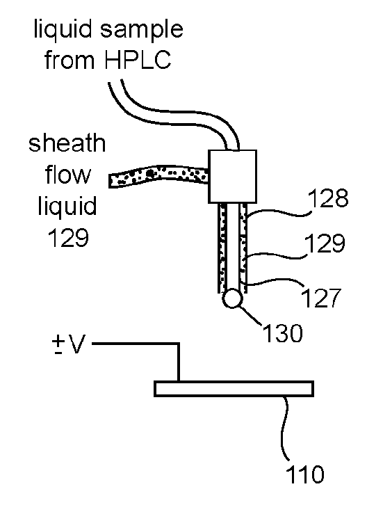
Application of a sheath flow is not possible in this case.

Method used


Image

  • Sample Deposition Method and System
  • Sample Deposition Method and System
  • Sample Deposition Method and System

Examples


Embodiment Construction

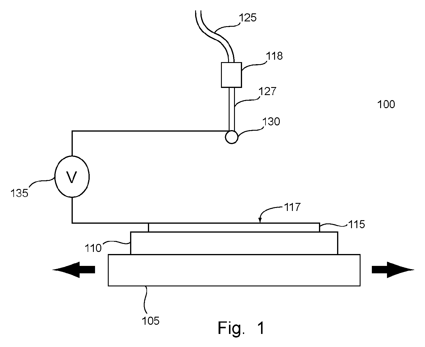
[0021]FIG. 1 is a simplified diagram illustrating an LC MALDI sample deposition system 100 according to an embodiment of the present invention. The system 100 includes a motion table 105 and a controller 107. The motion table 105 is movable at least in a longitudinal direction shown, under direction of the controller 107. The motion table 105 may also move laterally, vertically, or rotationally.

[0022] A sample plate holder 110 rides on the motion table 105, preferably fixed to the motion table 105. In one embodiment, the sample plate holder 110 is a subassembly of the motion table 105. Other configurations are possible; for example the sample plate holder 110 and the motion table 105 may be provided as a single unit. The sample plate holder 110 provides a base to which a sample plate 115 can be clamped. One or more sample plate holders can be situated on the motion table 105, thus providing an accurate mechanism for accurately and reliably positioning one or more sample plates on t...


PUM

PropertyMeasurementUnit
voltageaaaaaaaaaa
volumeaaaaaaaaaa
volumeaaaaaaaaaa

Abstract

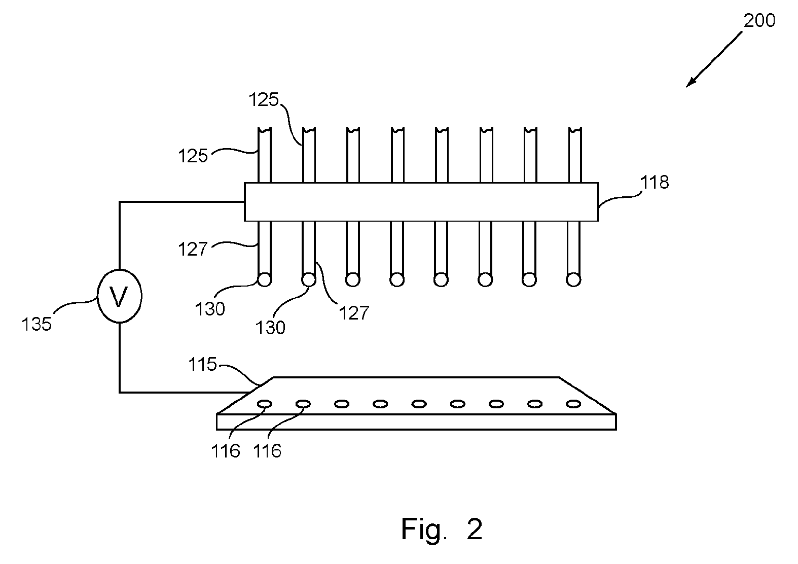
A method and system to deposit rapidly, accurately and efficiently liquid droplets onto a sample plate. A liquid from which the droplet is formed contains sample molecules, matrix molecules or a mixture of both sample and matrix molecules. A sample plate is positioned with respect to a position below a portion of the liquid, such as a droplet. A power supply forms an electric field between the sample plate and the liquid, which pulls the droplet to a target location on the sample plate. A plurality of capillary columns is provided for simultaneous or successive multiple depositions via application of one or more high voltage pulses between the liquid sample array and a sample plate.

Description

CROSS-REFERENCE TO RELATED APPLICATION [0001] This application is a continuation of application Ser. No. 09 / 765,207, filed Jan. 17, 2001.FIELD OF THE INVENTION [0002] The present invention relates to mass analysis. More particularly, the present invention relates to sample preparation and handling for mass spectrometry processes. DESCRIPTION OF THE RELATED ART [0003] Mass spectrometry (MS) is a method of mass analysis in which the chemical composition of a substance is identified by separating gaseous ions from the substance according to their mass-to-charge ratio. One type of ionization used in mass spectrometry is known as matrix-assisted laser desorption / ionization (MALDI). In MALDI, a sample and a matrix are co-crystallized from a liquid solution. The resulting co-crystal is irradiated with a laser, which causes the matrix molecules to absorb some of the incident energy. The absorbed energy causes some of the matrix and sample molecules to ionize and desorb into the gas phase. O...

Claims


Application Information

Patent Timeline
Patent Type & Authority Applications(United States)
IPC IPC(8): G01N27/62B01L3/02C40B60/14G01N1/00G01N1/18G01N30/80G01N30/84H01J49/04
CPCB01J2219/00369B01J2219/00371B01J2219/00653B01J2219/00691Y10T436/2575B01L2300/0838B01L2400/027C40B60/14B01L3/0268
Inventor BROCK, ANSGARSHAW, CHRISTOPHER M.DOWNS, ROBERT C
Owner IRM
Learn More