Backlight having a polarization separating element

a technology of separating element and backlight, which is applied in the field of backlight, can solve the problems of large cooling metal device not being fitted to the discharge tube, difficult to apply technology, and increasing the brightness of the backligh

Inactive Publication Date: 2005-10-27
SHARP KK
View PDF18 Cites 16 Cited by
  • Summary
  • Abstract
  • Description
  • Claims
  • Application Information

AI Technical Summary

Benefits of technology

[0030] It is an object of the present invention to provide a backlight capable of improving brightness by forming the most cooled portion at a predetermined position of a discharge tube, a display device and a production method thereof.
[0031] It is another object of the present invention to provide a backlight of a display device that has high utilization efficiency of light and can be used in a liquid crystal display device, for example.
[0032] It is still another object of the present invention to provide a display device capable of greatly changing brightness.

Problems solved by technology

These decreases cause a problem when the brightness of the backlight is to be increased.
However, it is difficult to apply the technology of fitting the cooling metal device for the discharge tube to the light source device of the backlight of the display device.
That is, as the tube diameter is small in the backlight of the display device and a reflector exists around the discharge tube, a large cooling metal device cannot be fitted to the discharge tube.
Also, leakage of current through the cooling metal device becomes large and, as the backlight of the display device has smaller power consumption than the fluorescent lamp for ordinary illumination, the discharge tube is likely to be excessively cooled.
For these reasons, this technology is not practical.
The light source device having a lamp heater that encompasses the fluorescent lamp cannot be used for the backlight of the liquid crystal display device.
Even when the waveform is symmetric, liquid mercury that is arbitrarily distributed in the discharge tube does not gather easily at one position in the discharge tube of a backlight using a thin glass tube of 5 mm or less, because the tube is thin and contains an amount of liquid mercury considerably greater than the amount of the gaseous mercury necessary for discharge.
However, it has been found that, in such a backlight, the desired improvement of brightness cannot be achieved unless liquid mercury is collected at the predetermined position.
The display device having the backlight containing the discharge tube involves another problem in that, even when the current supplied to the discharge tube is increased, the brightness does not increase much.
In the case of the liquid crystal display device using linearly polarized light, only a half of light of a non-polarized light source is utilized, hence, the utilization efficiency of light is low.
Therefore, the utilization efficiency of light is still limited.
In this case, however, the isotropic metal mirror absorbs the rays of light, so that utilization efficiency of light is limited, too.
However, the direct illumination type backlight cannot easily provide a liquid crystal display device that is thin and has low power consumption, and involves the problem that non-uniformity of brightness is likely to occur.
When the prism sheet and the scatter sheet containing the scattering material particles are used in combination, the production cost increases due to an increase in the cost of the sheet itself and an increase in the cost and the number of assembly steps.
Further, a problem of a drop in the yield occurs because dust appears between the prism sheet and the scatter sheet.
When the thickness of the light guide plate is reduced, however, the quantity of incoming light from the sides of the light guide plate becomes small.
Therefore, a reduction of thickness of the side edge type backlight is limited.

Method used


Image

  • Backlight having a polarization separating element
  • Backlight having a polarization separating element
  • Backlight having a polarization separating element

Examples


second embodiment

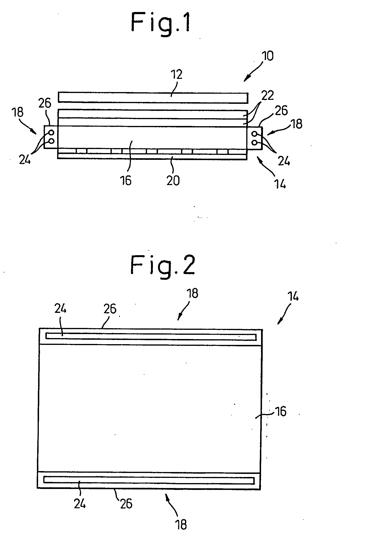
[0282]FIG. 42 is a sectional view showing the light source device of the present invention. FIG. 43 is a sectional view of the light source device shown in FIG. 42. FIG. 44 is a circuit diagram showing a fan controlling circuit in FIGS. 42 and 43. FIG. 45 explains the operation of the light source device shown in FIGS. 42 and 43. The light source device 18 in this embodiment includes a plurality of discharge tubes 24 and a reflector 26 covering all these discharge tubes 24. A fan 64 and a duct 66 are disposed to cool the discharge tubes 24. A hole 26a having a diameter of 0.5 mm is formed at the center of the bottom of the reflector 26.

[0283] Cooling air flows from the axial-flow fan (40mm in diameter) 64 fitted below the reflector 26 through the duct 66 and the hole 26a of the reflector 26 and is blown to the opposing portions of the two discharge tubes 24. As a result, one point of the mutually opposing sides of the two discharge tubes 24 becomes the most cooled portion as to the ...

third embodiment

[0285]FIG. 46 shows the backlight of the liquid crystal display device according to the present invention. Referring to FIG. 46, the backlight 70 of the liquid crystal display device includes a light guide plate 72, light source devices 74 disposed on either side of the light guide plate 72, an interference type mirror 76 disposed below the light guide plate 72 and a linear polarization separating element 78 disposed above the light guide plate 16. Each light source device 74 comprises discharge tubes and a reflector as described above. A conventional scattering layer is coated onto the acrylic light guide plate 72 by screen-printing.

[0286] The polarization separating element 78 comprises a cholesteric liquid crystal polymer film and broad-band 4 / 1 wavelength plates bonded to both surfaces of the cholesteric liquid crystal polymer film. The interference type mirror 76 has a multi-layered structure fabricated by laminating a plurality of transparent film layers having a light absorpt...

fourth embodiment

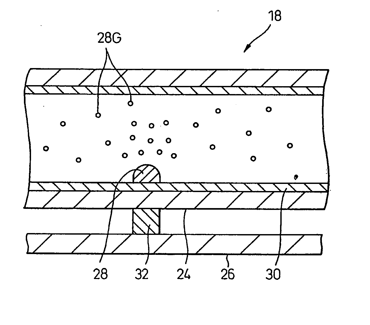
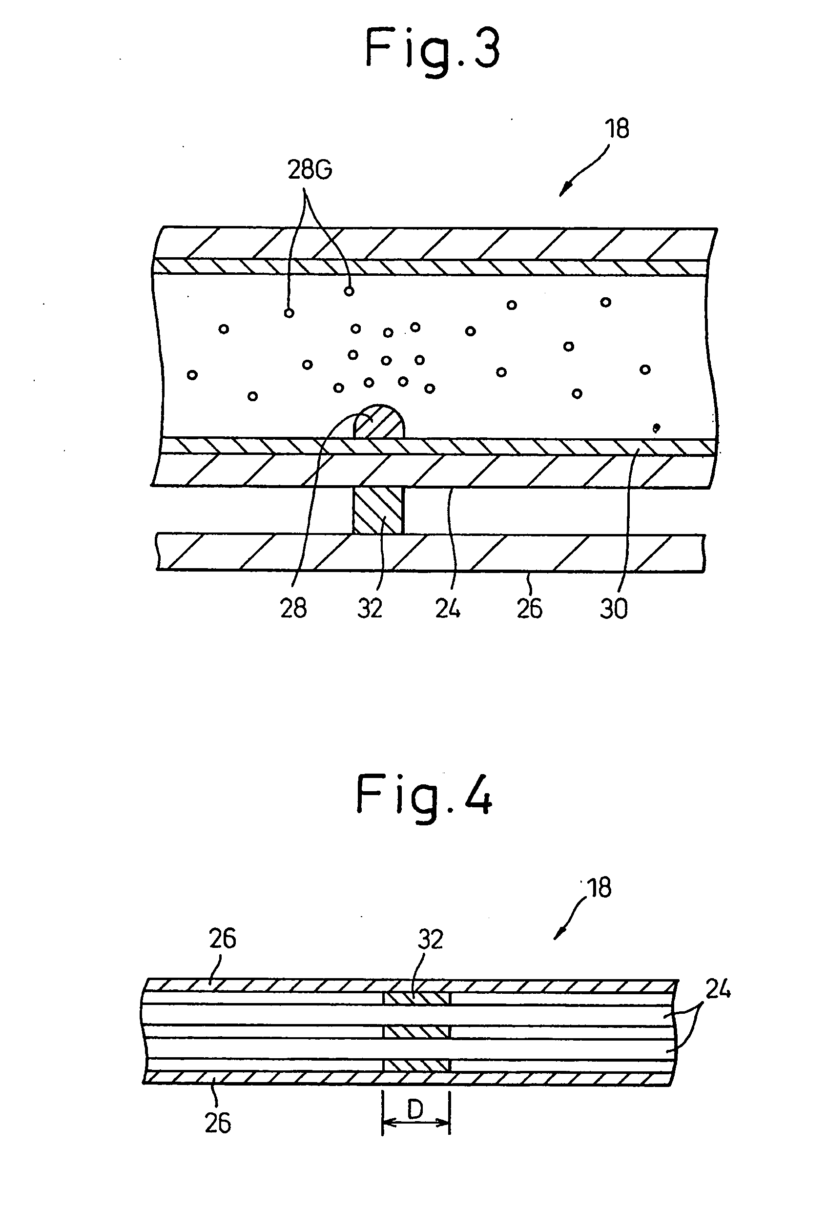
[0308]FIG. 57 shows the light source device 18 of the backlight according to the present invention. The light source device 18 includes a discharge tube 24 containing mercury 28, a reflector 26 and a heat conduction member 32 interposed between the discharge tube 24 and the reflector 26. The discharge tube has electrodes 25. A fluorescent material 30 is coated to the inner surface of a glass tube constituting the discharge tube 24. The heat conduction member 32 is a cooling device defining a first position of the discharge tube 24 as a most cooled portion (the position of the discharge tube 24 at which the heat conduction member 32 is disposed is called the first position). The backlight is arranged such that liquid mercury 28 is collected at the first position in the discharge tube 24, and the discharge tube 24 emits the light with the highest brightness based on the temperature of the first position. In this embodiment, liquid mercury 28 is gathered at the first position in the di...


PUM

PropertyMeasurementUnit
diameteraaaaaaaaaa
temperatureaaaaaaaaaa

Abstract

A display device includes a backlight having a discharge tube and a reflector. A heat conduction member is attached to the reflector in contact with the discharge tube, so that a part of the discharge tube is locally cooled by the heat conduction member. Liquid mercury is collected at a first position in the discharge tube, and the backlight is assembled so that the heat conduction member or other cooling device is located at the first position. Also, the display device includes an optical sheet having a diffusion portion having projections containing scattering material particles.

Description

BACKGROUND OF THE INVENTION [0001] 1. Field of the Invention [0002] This invention relates to a backlight, of a display device, having a discharge tube emitting light during discharge in a lean gas and to a method of manufacturing a backlight, and a display device. [0003] 2. Description of the Related Art [0004] A backlight, of a display device such as a liquid crystal display device, uses a light source device comprising one or a plurality of discharge tubes and a reflector. The discharge tube is a cold cathode tube, in which mercury and argon (Ar) gas or neon (Ne) gas are sealed and a fluorescent material is coated on the tube wall. Mercury gas generates ultraviolet light during discharge, and the ultraviolet light impinges against the fluorescent material and generates visible light. [0005] The backlight of most of liquid crystal display devices includes a light guide plate. In one example, two light source devices are disposed on opposite sides of the light guide plate in such a...

Claims


Application Information

Patent Timeline
Patent Type & Authority Applications(United States)
IPC IPC(8): G02F1/13357F21V8/00F21V29/00G02B6/00H01J61/52H01J61/72
CPCF21V29/004F21V29/85F21V29/02G02B6/0036G02B6/0038G02B6/004G02B6/0051G02B6/0056G02B6/0065G02B6/0071G02B6/0085G02F1/133604G02F1/133605G02F1/133606G02F1/133608G02F2001/133607G02F2001/133628H01J61/523H01J61/72F21V29/54F21V29/71F21V29/763F21V29/006F21V29/67F21V29/70G02F1/133607G02F1/133628B82Y40/00G02F1/1335
Inventor HAYASHI, KEIJIKOBAYASHI, TETSUYAHAMADA, TETSUYAGOTOH, TAKESHISUZUKI, TOSHIHIROSUGAWARA, MARISOTOKAWA, AKIOHACHISUKA, SEIJI
Owner SHARP KK
Why Eureka
Try Eureka