

Method of reinforcing an embedded cylindrical pipe
a technology of reinforcing pipes and cylindrical pipes, applied in the direction of pipe laying and repair, mechanical equipment, building repairs, etc., can solve the problems of not being designed to carry pressure, process can then accelerate, and exposed to corrosion risk, etc., to reduce the contamination of the liner through external agents, reduce the risk of corrosion, and reduce the effect of negative moments
- Summary
- Abstract
- Description
- Claims
- Application Information
AI Technical Summary
Benefits of technology
Problems solved by technology
Method used
Image

Examples
Embodiment Construction
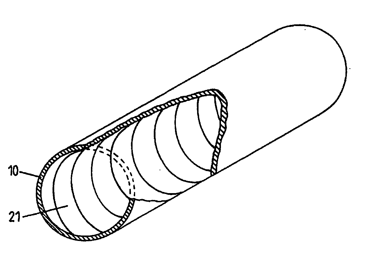
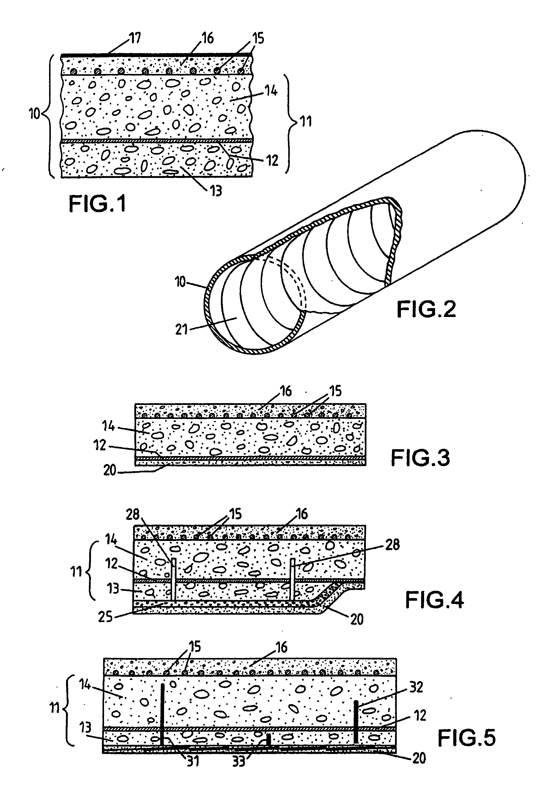
[0034] Referring to the figures, a composite reinforcement 20 is arranged inside a damaged underground pipe. This reinforcement is composed of a band of fibers 21 wound according to a helicoidal path along the internal side of the pipe, as illustrated by FIG. 2 (in which the ground material surrounding the pipe is not shown).
[0035] The pipes in question are preferably embedded cylinder pipes as described previously with reference to FIG. 1. Their diameter is sufficient to allow the intervention of a human operator inside, for example 1.5 to 4.5 m. The service pressure in the pipe can be up to around 0.5 MPa.
[0036] The reinforcement fibers of the band 21 are made from a resistant material (resistance to breaking typically greater than 1500 MPa) and are of a high elastic module (typically between 100 and 400 GPa). Carbon fibers will generally be used for this (resistance to breaking in the range of 3000 MPa). By way of example the bands 21 have a width of 600 mm and they are compose...
PUM
 Abstract
Description
Claims
Application Information