Process for metallic contamination reduction in silicon wafers

a technology of metallic contamination and silicon wafers, which is applied in the manufacturing of semiconductor/solid-state devices, basic electric elements, electric devices, etc., can solve the problems of deformation of dislocations and other defects, degraded silicon device performance, and useless integrated circuits prepared from silicon wafers

Active Publication Date: 2005-11-10
GLOBALWAFERS CO LTD
View PDF4 Cites 35 Cited by
  • Summary
  • Abstract
  • Description
  • Claims
  • Application Information

AI Technical Summary

Benefits of technology

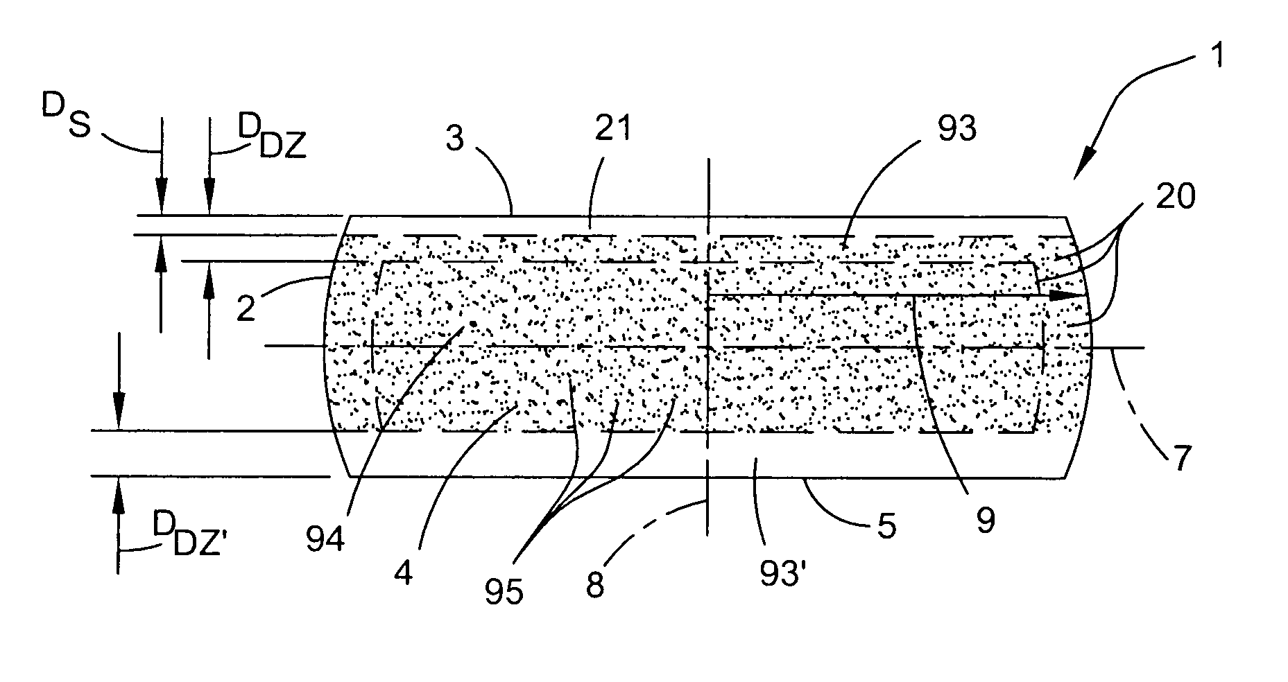
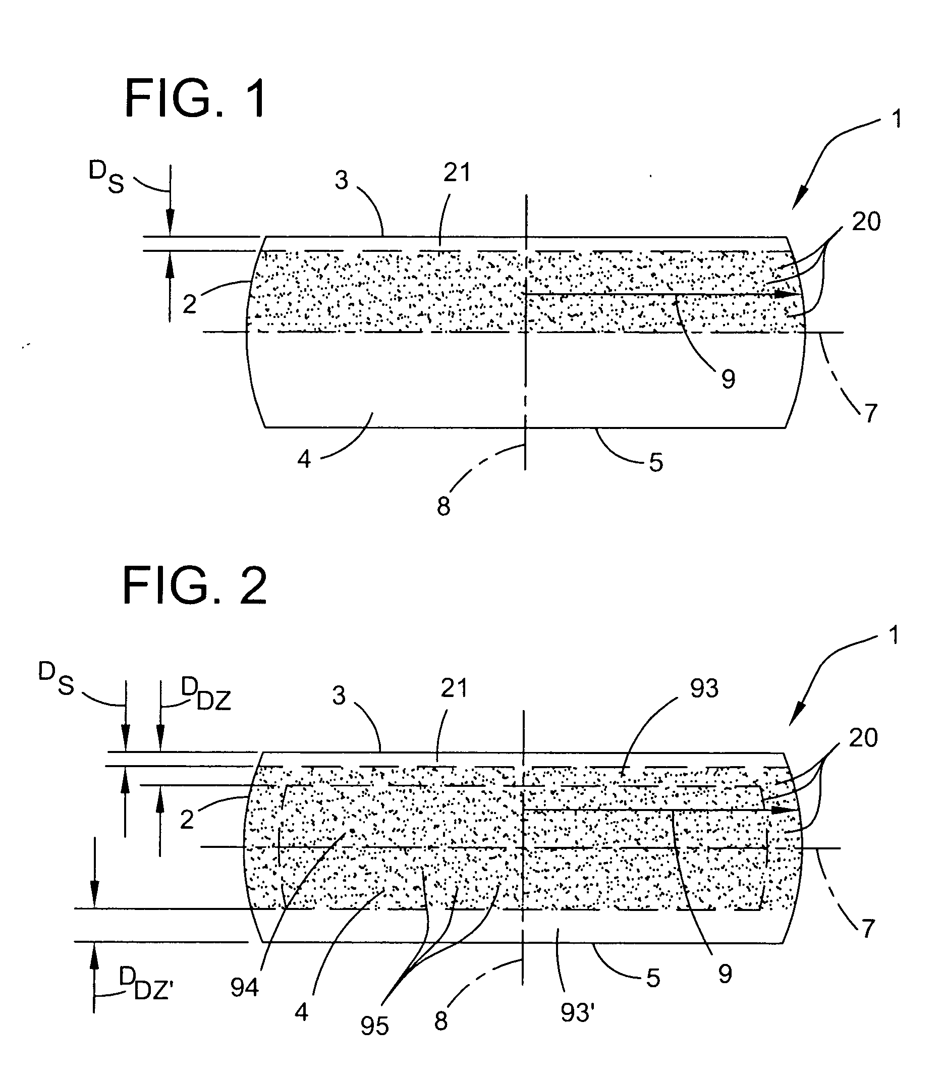
[0011] Additionally, the present invention is directed to a process for process for removing a contaminant selected from among copper, nickel, and a combination thereof from a silicon wafer having a silicon wafer surface and a silicon wafer interior. The process comprises increasing the temperature of the silicon wafer to an annealing temperature that is at least about 1100° C. while exposing the silicon wafer to a heating-cooling ambient comprising argon. The silicon wafer is annealed by exposing the silicon wafer to an annealing ambient selected from the group consisting of hydrogen, helium, neon, argon, krypton, xenon, and combinations for a duration that is between about 30 minutes and about 90 minutes as the silicon wafer is at the annealing temperature to remove silicon oxide from the silicon wafer surface and to facilitate the migration of silicon atoms to exposed agglomerated vacancy defects at the silicon wafer surface thereby reducing the size of the exposed agglomerated vacancy defects. The temperature of the silicon wafer is decreased from the annealing temperature to an oxidation initiation temperature that is no greater than about 800° C. while exposing the silicon wafer to the heating-cooling ambient. As the temperature of the wafer is decreased from the oxidation initiation temperature, the silicon wafer is exposed to an oxidizing ambient comprising oxygen at a concentration that is between about 10 and about 100 ppm to form an oxide layer on the silicon wafer surface and a strain layer at an interface between the oxide layer and the silicon wafer interior. The temperature decrease of the silicon wafer is controlled to permit diffusion of atoms of the contaminant from the silicon wafer interior to the strain layer. The silicon wafer is cleaned to remove the contaminant that diffused to the strain layer from the silicon wafer.

Problems solved by technology

Silicon device performance is degraded by metallic contaminants.
The precipitates often result in the formation of dislocations and other defects.
The precipitates and their associated dislocations and defects, if present in the device fabrication region of the wafer, may render integrated circuits prepared from the wafer useless.
Additionally, copper silicide precipitates may form what are referred to as haze defects because, upon being subjected to a common etching treatment and bright light inspection, the precipitates cause defects that appear as a haze on the surface of the wafer.
Thus, wafers which meet a target specification for surface copper concentration immediately after cleaning may fail to meet this specification as soon as five to ten months later.
Although modifying polishing mixtures have tended to reduce the degree of copper contamination in silicon wafers, it typically has not been sufficiently effective to negate the need for other copper reduction methods.
Additionally, the ever more stringent limitations being placed upon metallic contaminant levels in silicon wafers by integrated circuit manufactures makes relying on polishing mixture modifications a significantly more costly option for controlling metallic contamination in silicon wafers.
Gettering techniques, however, have not proven to be an entirely acceptable solution for controlling metallic contaminants.
Additionally, it is possible for the defects introduced into silicon as gettering sinks to reduce the quality of silicon by, for example, reducing minority carrier recombination lifetime.
Although these low-temperature anneals may be used to effectively remove copper from a single silicon wafer, they have not been implemented in a typical manufacturing process because they would significantly decrease throughput and would greatly increase the cost of a wafer.
For this reason, these low-temperature anneals have been limited to laboratory and testing applications.

Method used


Image

  • Process for metallic contamination reduction in silicon wafers
  • Process for metallic contamination reduction in silicon wafers

Examples


examples

[0060] The annealing furnace used was an ASM model A412 vertical furnace equipped with a high purity TSQ-10 quartz tube manufactured by Toshiba Ceramics and a 125 slot silicon carbide boat design to hold 200 mm wafers. The silicon carbide boat had a high purity silicon carbide coating deposited thereon by chemical vapor deposition by AG Electronic Materials. After performing the annealing process, the wafers were cleaned with a SubMicron Systems wet bench and standard SC1 and SC2 cleaning solutions as described in greater detail above.

[0061] Each test group of wafers was subjected to a standard hydrogen anneal. Specifically, the wafers (with native oxide layers) were placed in the furnace and heated to a temperature of about 1200° C., held at 1200° C. for about one hour, and then cooled. A plot of the temperature as a function of anneal time from between about 450° C. to the maximum temperature and back to about 450° C. generally resembles a parabola except that there is an extende...


PUM

PropertyMeasurementUnit
temperatureaaaaaaaaaa

Abstract

A process for removing a contaminant selected from among copper, nickel, and a combination thereof from a silicon wafer having a surface and an interior. The process comprises cooling the silicon wafer in a controlled atmosphere from a temperature at or above an oxidation initiation temperature and initiating a flow of an oxygen-containing atmosphere at said oxidation initiation temperature to create an oxidizing ambient around the silicon wafer surface to form an oxide layer on the silicon wafer surface and a strain layer at an interface between the oxide layer and the silicon wafer interior. The cooling of the wafer is also controlled to permit diffusion of atoms of the contaminant from the silicon wafer interior to the strain layer. Then the silicon wafer is then cleaned to remove the oxide layer and the strain layer, thereby removing said contaminant having diffused to the strain layer.

Description

BACKGROUND OF THE INVENTION [0001] The present invention generally relates to the preparation of semiconductor material substrates, especially silicon wafers, which are used in the manufacture of electronic components. More particularly, the present invention relates to a process for thermally treating or annealing one or more silicon wafers to reduce the concentration of metal contaminants such as copper from the wafer interior or bulk. Additionally, the process of the present invention may be performed in a manner that reduces the concentration or size of agglomerated vacancy defects on the surface and in the bulk of one or more silicon wafers. [0002] Silicon device performance is degraded by metallic contaminants. Transition metals, including copper, iron and nickel, may dissolve and diffuse during the normal thermal cycles associated with integrated circuit manufacturing conditions. While cooling from the temperatures associated with integrated circuit manufacturing, copper and ...

Claims


Application Information

Patent Timeline
Patent Type & Authority Applications(United States)
IPC IPC(8): H01L21/322H01L21/324
CPCH01L21/3221H01L21/324H01L21/3225H01L21/322
Inventor SHIVE, LARRY W.GILMORE, BRIAN L.
Owner GLOBALWAFERS CO LTD
Why Eureka
Try Eureka