Image forming method

a technology of image bearing and forming method, which is applied in the direction of instruments, electrographic process apparatus, corona discharge, etc., can solve the problems of ozone generation, image deletion, and sticking of toner onto the surface of the image bearing member, and achieves low running cost, high image quality, and long service life

Inactive Publication Date: 2005-11-17
CANON KK
View PDF7 Cites 16 Cited by
  • Summary
  • Abstract
  • Description
  • Claims
  • Application Information

AI Technical Summary

Benefits of technology

[0015] An object of the present invention is to provide an image forming method free from the aforementioned drawbacks.
[0016] More specifically, the invention is to provide an image forming method of a long service life, a high image quality and a low running cost, capable of maintaining a stable cleaning performance over a prolonged period without causing an image smearing phenomenon, even with a image bearing member such as a photosensitive member, of a high durability (high strength and high abrasion resistance).
[0017] The present inventors, as a result of intensive investigations, have found that a following configuration can provide an image forming method of a long service life, a high image quality and a low running cost, capable of maintaining a stable cleaning performance over a prolonged period without causing an image smearing phenomenon, even with a image bearing member such as a photosensitive member, of a high durability (high strength and high abrasion resistance), and have thus made the present invention.
[0020] Thus the present invention provides an image forming method of a long service life, a high image quality and a low running cost, capable of maintaining a stable cleaning performance over a prolonged period without causing an image smearing phenomenon, even with a image bearing member such as a photosensitive member, of a high durability (high strength and high abrasion resistance).

Problems solved by technology

The corona discharge apparatus is effective for charging the surface of the image bearing member at a specified potential, but involves drawbacks of requiring a high voltage source and generating ozone.
Also as the surface of the image bearing member is not easily scraped, the discharge products are not easily removable thereby leading to an image deletion.
However, such heater, also requiring thermal control means, complicates the configuration of the image forming apparatus, also leading to a complication in the system against the trend of the copying machine and the printer toward a compacter and more personal system.
Also the heating of the image bearing member, close to a glass transition temperature (Tg) of the toner, may cause a sticking of the toner onto the surface of the image bearing member.
On the other hand, even when the elimination from the surface of the elastic roller is achieved sufficiently, in case the transfer residual toner is present only in a small amount, the elastic roller comes into direct contact and rubbing with the surface of the image bearing member, thus damaging the surface thereof.
However, in case an aforementioned contact charging apparatus is employed as the charging means, the abrasive leaking through the cleaning blade may contaminate the contact charging apparatus, thereby inducing an uneven charging to cause an image defect.

Method used


Image

  • Image forming method
  • Image forming method
  • Image forming method

Examples


example 1

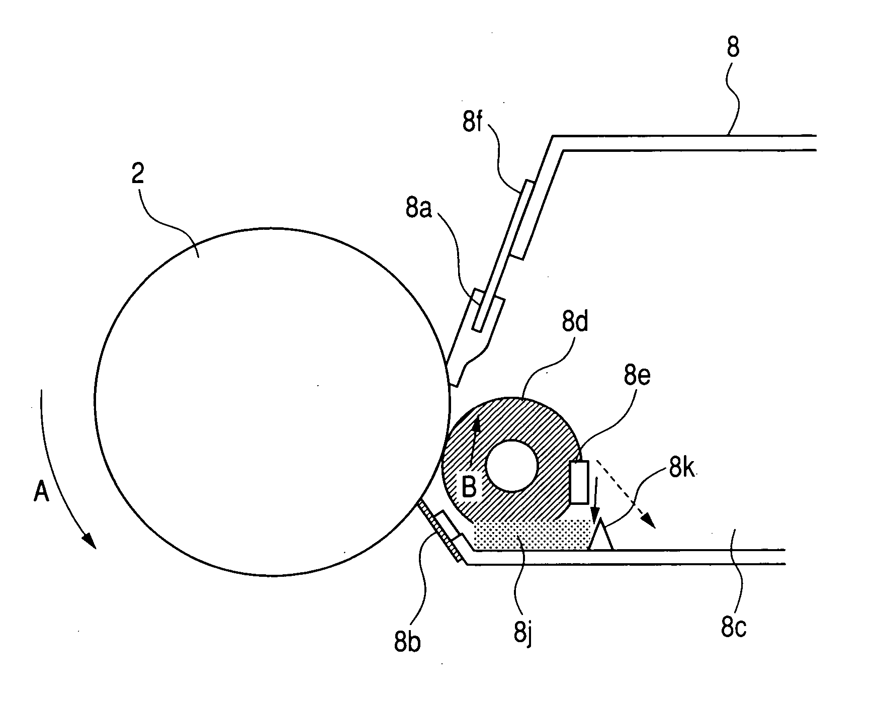
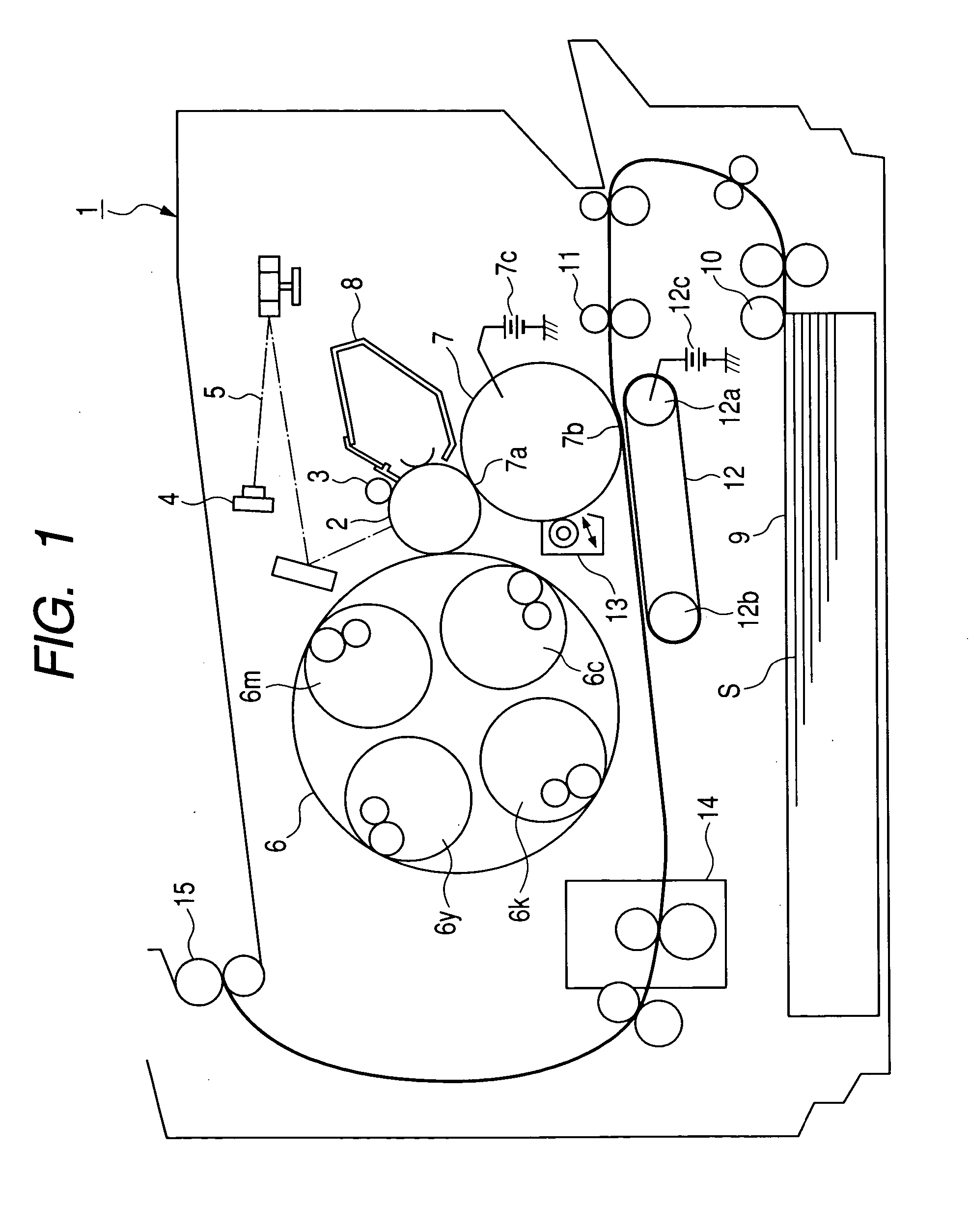
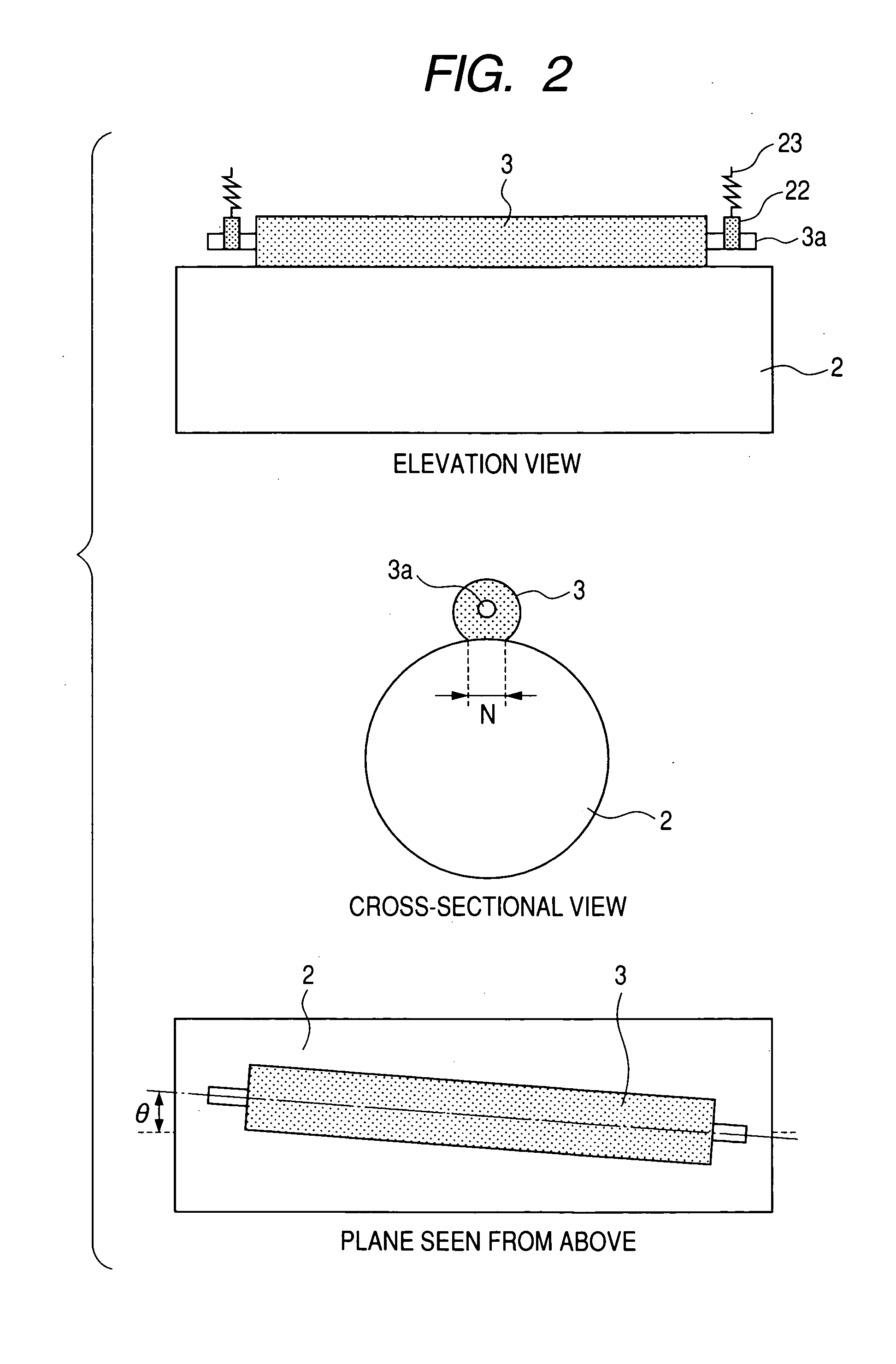
[0118] An image forming apparatus employed in the present example is approximately same as that in the foregoing embodiment. As the abrasive particles, strontium titanate having an average primary particle size of 100 nm, a cubic and / or rectangular parallelepiped shape and a perovskite crystalline structure was employed. In the abrasive particles, a content of particles or aggregates of a size of 600 nm or larger was 1% in number or less. In the abrasive particles of the present example, the cubic and / or rectangular parallelepiped shape and the perovskite crystalline structure allow to effectively eliminate charging products on the surface of the photosensitive member. Also a supply member for the abrasive particles was provided in the cleaning container, as illustrated in FIG. 3. The cleaning apparatus 8 is constituted of a cleaning blade 8a serving as cleaning means supported by a metal plate 8f, a toner collecting sheet 8b, a used toner recovery container 8c, a fur brush 8d const...

example 2

[0153] The present example employed, as the abrasive particle supply method, a method of externally adding the abrasive particles to the developing toner and supplying them under a developing operation. The cleaning apparatus 8 had a structure in Example 1, from which the rotary fur brush 8d constituting the abrasive particle supplying member and the abrasive particles 8j were removed. Other structures are same as those in Example 1.

[0154] Table 4 shows a relationship between a ratio of the abrasive particles externally added to the toner, and a mixing ratio of the abrasive particles present in the transfer residual (used) toner.

TABLE 4(Mixing ratio of abrasive particles in transfer residual toner)External addition rate0.10.50.71.01.52.0(weight %) of abrasiveparticles in developing tonerMixing ratio (weight %) of0.21.01.52.03.04.5transfer residual toner andabrasive particles = abrasiveparticle supply amount A

[0155] In the above-described configuration, an image smearing in an env...

example 3

[0157] The present example employed, as the abrasive particle supply method, both a method of externally adding the abrasive particles to the developing toner and supplying them under a developing operation and a method of providing an abrasive particle supplying member in the developing container. The cleaning apparatus 8 had the same structure as in Example 1. An image smearing in an environment of a temperature of 30° C. and a humidity of 80%, and a charging unevenness and a cleaning property in an environment of a temperature of 23° C. and a humidity of 5% were evaluated in a durability test of 10,000 prints by varying the abrasive particle supply amount A (weight %), the contact pressure B (g / cm) of the cleaning blade and the crossing angle θ.

[0158] As a result, a satisfactory cleaning property could be obtained without an image smearing under a high humidity condition or an image unevenness resulting from contamination on the contact charging roller under a low humidity condi...


PUM


Abstract

The invention is to provide an image forming method of a long service life, a high image quality and a low running cost, capable of maintaining a stable cleaning performance over a prolonged period without causing an image deletion phenomenon, even with a image bearing member such as a photosensitive member, of a high durability (high strength and high abrasion resistance). The invention provides an image forming method characterized in that the image bearing member has a universal surface hardness HU of 150 to 220 N / mm2 and an elastic deformation ratio We of 40 to 65%, and, for a crossing angle θ (°) between a rotary axis of the contact charging roller and a rotary axis of the image bearing member, for a ratio A (weight %) of the transfer residual toner and the abrasive particles and for a contact pressure B (g / cm) of the cleaning blade, HU, We, A, B and θ satisfy the following relations (I), (II) and (III): (1 / 6000)×HU×We≦A×B  (I) A / B≦θ  (II) 10≦B≦50  (III).

Description

BACKGROUND OF THE INVENTION [0001] 1. Field of the Invention [0002] The present invention relates to an image forming method utilizing an electrophotographic process. [0003] 2. Related Background Art [0004] An electrophotographic system is widely employed in an image forming apparatus for example a copying apparatus, a printer or a facsimile for forming an image on a recording medium such as paper. In the electrophotographic system, an image bearing member such as a photosensitive member is uniformly charged on a surface thereof, which is irradiated with a laser light to generate a potential difference between an irradiated portion and a non-irradiated portion thereby forming an electrostatic latent image. Then a charged toner is deposited on the surface of the image bearing member, thereby developing the electrostatic latent image on the surface of the image bearing member as a toner image. Thereafter, the toner image is transferred onto a recording medium to form an image thereon....

Claims


Application Information

Patent Timeline
Patent Type & Authority Applications(United States)
IPC IPC(8): G03G15/00G03G15/02G03G21/00
CPCG03G21/0011
Inventor MIURA, MASAHARUKAWAKAMI, HIROAKI
Owner CANON KK
Why Eureka
Try Eureka