
Pattern forming method

a technology of pattern and forming method, which is applied in the direction of photomechanical equipment, instruments, originals for photomechanical treatment, etc., can solve the problems of failure to have sufficient performance and stability within the required time period, difficulty in stabilizing the production cost or quality of the apparatus and materials, and failure to procure the exposure equipment. , to achieve the effect of lessening the fear of contamination or corrosion of the immersion exposure machin

Inactive Publication Date: 2005-11-17
FUJIFILM CORP +1
View PDF17 Cites 41 Cited by
  • Summary
  • Abstract
  • Description
  • Claims
  • Application Information

AI Technical Summary

Benefits of technology

[0019] By taking account of these problems in conventional techniques, an object of the present invention is to provide a resist pattern forming method suitable for immersion exposure, where the immersion time dependency of resist sensitivity can be decreased and the amount of acid dissolved out into an immersion liquid can be reduced.
[0032] According to the present invention, a resist pattern forming method where the immersion time dependency of resist sensitivity in the immersion exposure is low and by virtue of decrease in the amount of acid dissolved out from the resist surface at the immersion exposure, the fear of contamination or corrosion of the immersion exposure machine is lessened, can be provided.

Problems solved by technology

However, the lens material used for the exposure apparatus so as to realize shorter wavelength and the material used for the resist are very limited and therefore, it is extremely difficult to stabilize the production cost or quality of the apparatus and materials.
This may lead to a failure in procuring the exposure apparatus and resist having sufficiently high performance and stability within a required time period.
However, the additive is not disclosed or the resist suitable for immersion exposure techniques is not discussed.
In other words, a region which is repeatedly immersed in water is generated depending on the position in the wafer plane and this causes a fear that the resist performance is changed depending on the position, that is, the uniformity in the wafer plane is impaired.
If a large amount of generated acid dissolves out from the resist surface into the immersion liquid at the immersion exposure, the objective lens of the exposure machine may be contaminated.

Method used


Image

  • Pattern forming method
  • Pattern forming method
  • Pattern forming method

Examples


examples

[0078] The present invention is described in greater detail below by referring to Examples, but the present invention is not limited thereto.

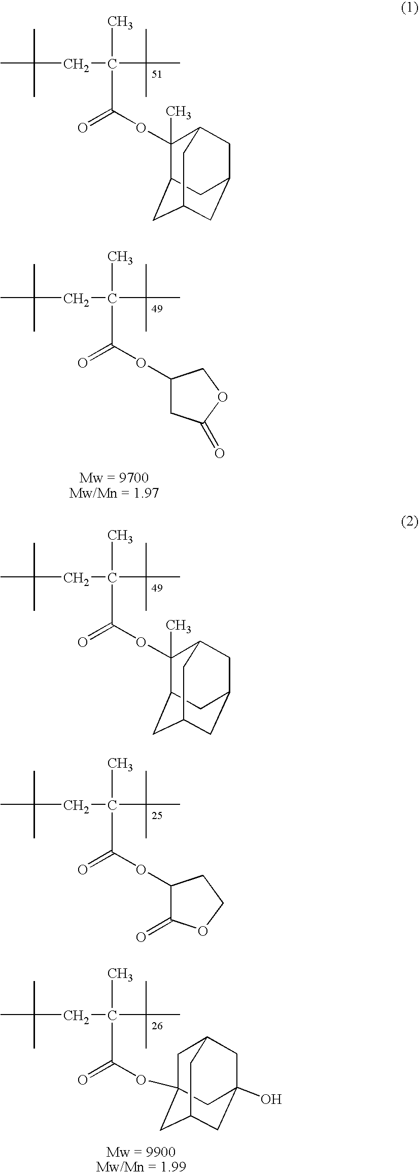
[0079] (Synthesis of Resin (1) for Resist Composition)

[0080] 2-Methyl-2-adamantyl methacrylate and mevalonic lactone methacrylate were charged at a ratio of 45 / 55 (by mol) and dissolved in tetrahydrofuran to prepare 100 mL of a solution having a solid content concentration of 20 weight %. Subsequently, 2 mol % of polymerization initiator V-65 produced by Wako Pure Chemical Industries, Ltd. and 4 mol % of mercaptoethanol were added to the solution obtained above, and the resulting solution was added dropwise to 10 mL of tetrahydrofuran heated to 60° C. over 2 hours in a nitrogen atmosphere. After the completion of dropwise addition, the reaction solution was heated and stirred for 6 hours. When the reaction was completed, the reaction solution was cooled to room temperature and crystallized from 3 L of methanol, and the precipitated white powd...


PUM


Abstract

A pattern forming method includes (a) a step of forming a resist film on a substrate, (b) a pre-wet step of spreading a pre-wet solution on the resist film and after a fixed time, removing the pre-wet solution, and (c) a step of subjecting the resist film on the substrate to exposure through an immersion liquid.

Description

[0001] This application is based on Japanese Patent application JP 2004-146023, filed May 17, 2004, the entire content of which is hereby incorporated by reference. This claim for priority benefit is being filed concurrently with the filing of this application. BACKGROUND OF THE INVENTION [0002] 1. Technical Field of the Invention [0003] The present invention relates to a pattern forming method utilizing a resist composition used in the process of producing a semiconductor such as IC or producing a circuit board of liquid crystal, thermal head or the like or in the lithography step of other photo-application processes. More specifically, the present invention relates to a pattern forming method utilizing a resist composition suitable for exposure by an immersion-type projection exposure apparatus using a light source of emitting far ultraviolet light at a wavelength of 300 nm or less. [0004] 2. Description of the Related Art [0005] Along with the progress in the development of refin...

Claims


Application Information

Patent Timeline
IPC IPC(8): G03F7/00G03F7/16G03F7/20
CPCG03F7/168G03F7/70341G03F7/2041
Inventor INABE, HARUKIKANNA, SHINICHIKANDA, HIROMI
Owner FUJIFILM CORP
Learn More