
Devices and methods for measuring and enhancing drug or analyte transport to/from medical implant

a technology of analyte and drug, which is applied in the field of medical devices implantation, can solve the problems of adversely affecting the transport of drug from the device to the device, formation of fibrous tissue capsules, and inability to accurately measure the effect of drug transport, and achieves the effect of enhancing the transport of drug molecules and enhancing the transport of drug

Inactive Publication Date: 2005-12-01
MICROCHIPS INC
View PDF99 Cites 182 Cited by
  • Summary
  • Abstract
  • Description
  • Claims
  • Application Information

AI Technical Summary

Benefits of technology

[0008] In one embodiment, a method is provided for enhancing the transport of a drug from an implanted drug delivery device across a tissue capsule. In this embodiment, the method includes controllably releasing a drug formulation from a plurality of discrete reservoirs located in medical device implanted in a patient; and controllably releasing an effective amount of a transport enhancer from said medical device implanted in a patient, to facilitate transport of the released drug formulation through a fibrous tissue capsule, if any, which exists around the device at the site of implantation.
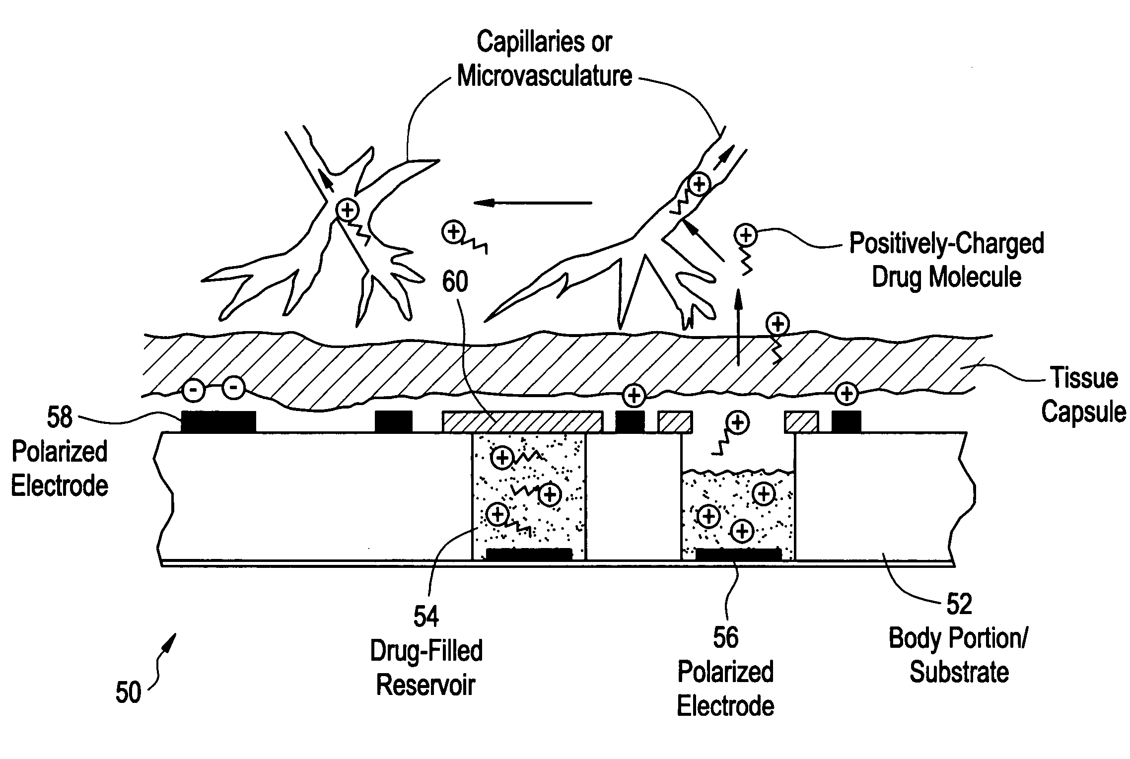
[0015] In another aspect, a method is provided for enhancing the transport of drug from an implanted drug delivery device and across a tissue capsule, wherein the method includes the steps of controllably releasing a drug formulation, which comprises charged drug molecules, from a plurality of discrete reservoirs of a medical device implanted into a patient, the release of the drug and the release of the enhancing agent being from one or more reservoirs located in the device; and utilizing an electromotive method to enhance transport of the charged drug molecules through a tissue capsule, if any, surrounding the implanted medical device. In one example, the electromotive method includes iontophoresis. In one embodiment, an external surface of the medical device is charged by an electronic component therein, or thereon, creating a driving force effective to propel the drug molecules through tissue capsule surrounding the implanted medical device.

Problems solved by technology

Implantation of medical devices can induce inflammation and fibrosis when the body responds to the foreign object.
Fibrosis results in the formation of a fibrous tissue capsule in the proximity of the device.
During the lifetime of an implanted drug delivery device or biosensor, the structure of the fibrous tissue capsule may change, and such changes may adversely affect the transport of drug from the device, or the transport of an analyte to the device.
In addition, drugs that are cleared rapidly from the circulation, such as prostacyclins, may not be able to achieve therapeutic concentrations if they are released through the tissue capsule too slowly.
Similarly, a tissue capsule may slow the diffusion of analytes or other substances to sensors contained in or on the implanted device.
Slowing the diffusion rate of an analyte to a sensor will increase the time required to detect changes in the analyte or decrease the sensitivity of the sensor, either of which may render the sensor ineffective for analyte or therapeutic drug monitoring.
For example, a tissue capsule may slow the rate of glucose transport to a glucose sensor, which introduces a time lag and results in a discrepancy between the actual and measured glucose level in the body.
In this case, if a Type I diabetic were to make decisions on insulin dosing using the measured glucose level, they would be at risk of over or under dosing themselves, which could lead to a dangerous condition such as hypoglycemia.
Current methodologies have been more or less limited to (1) in vitro tests (e.g., where the tissue capsule is removed from the animal, placed in a diffusion cell, and the transport through the ‘non-living’ capsule is measured) or (2) infusion of markers into the animal (e.g., the marker is infused into the animal, the animal is sacrificed, the tissue capsule is removed and frozen, and the capsule is analyzed for marker content and location) limiting analysis to only one time point per animal, which is highly inefficient and wasteful.
These methods do not allow multiple or real time quantitative measurements to occur in situ or in vivo, which would provide the most realistic and reliable data.

Method used


Image

  • Devices and methods for measuring and enhancing drug or analyte transport to/from medical implant
  • Devices and methods for measuring and enhancing drug or analyte transport to/from medical implant
  • Devices and methods for measuring and enhancing drug or analyte transport to/from medical implant

Examples


example 1

Testing Device Design

[0145] The testing device would be in the form of a closed loop implant test system. In this design, a microchip device will be attached along a length of metabolite impermeable tubing, substantially as shown in FIG. 13. The microchip will contain active reservoir caps that can be selectively disintegrated at any time following implantation. The design may include the placement of suture loops if necessary or the placement of surgical mesh to reduce implant motion which will disrupt the normal wound healing response. The microchip will be sealed to the test loop system, and will include the electrical system, used to activate the membranes and open the reservoirs and the percutaneous connectors.

[0146] The testing device will be implanted into the subcutaneous space of the animal model, and the incision allowed to heal for a pre-determined period of time. The wiring and tubing will be accessible through a percutaneous connector. Then, at selected times, the res...

example 2

Leak Testing

[0147] In vitro testing of the testing device to be used in animals is important prior to implantation. A system leak test will be performed. The device will be placed in a saline solution. The membranes of the device will remain intact throughout the experiment. An easily detectable compound (e.g. radio-labeled mannitol) will be pushed through the system using a pump. At pre-determined time-points, the saline will be sampled and analyzed for any evidence of the molecule pushed through the system. This experiment must be repeated on multiple devices to ensure proper device assembly. FIG. 15 illustrates the test set up.

example 3

In Vitro Testing

[0148] Prior to any in vivo studies, the device will be tested in vitro to ensure device functionality. The device will be placed in a saline solution. A saline solution will be pumped through the system. The microchip reservoirs will then be ablated, opening access to the test loop system. A specified amount of an easily detected compound will be injected into the saline solution in which the device is immersed. Saline solution will be pumped through the system and collected at certain time intervals. The outlet saline will be analyzed for the compound concentration at predetermined time-points. This experiment should be repeated on multiple devices to ensure proper device function. The in vitro test will provide a best case experiment for comparison purposes. FIG. 16 illustrates the test set up. Repeatable results should be obtained prior to in vivo experimentation.

[0149] In addition to testing functionality, these test methods will be useful for assessing the pe...


PUM


Abstract

Methods and devices are provided for enhancing mass transport through any fibrous tissue capsule that may form around an implanted medical device following implantation. Methods and devices are also provided to enhance vascularization around the implanted device, which also will aid in mass transport to / from the device. The device preferably comprises multiple reservoirs containing (i) a drug formulation for short- or long-term, controlled drug delivery, (ii) sensors for sensing an analyte in the patient, or (iii) a combination thereof.

Description

CROSS-REFERENCE TO RELATED APPLICATIONS [0001] This application claims the benefit of U.S. Provisional Applications No. 60 / 575,946, filed Jun. 1, 2004; No. 60 / 635,780, filed Dec. 13, 2004; No. 60 / 593,832, filed Feb. 17, 2005; and No. 60 / 655,785, filed Feb. 24, 2005. The applications are incorporated herein by reference in their entirety.BACKGROUND OF THE INVENTION [0002] This invention is generally in the field of implantable medical devices. In particular, the invention relates to apparatus and methods for measuring and modulating mass transport of drug or analyte through a tissue capsule structure to / from an implanted medical device, and for controlling tissue / implant interactions for improved function, integration, and useful life of the implant. [0003] A variety of medical devices have been or are being developed for implantation into human and animal patients. Examples include drug delivery devices, biosensors, orthopedic prosthesis, and the like. Implantation of medical device...

Claims


Application Information

Patent Timeline
IPC IPC(8): A61B5/00A61B5/03A61B5/042A61B5/07A61F2/06A61M31/00A61M37/00A61N1/05A61N1/30
CPCA61B5/03A61N1/306A61B5/042A61B5/076A61B5/14528A61B5/14532A61B5/14546A61B5/1486A61B5/686A61K9/0009A61K9/0024A61K9/0097A61M37/00A61N1/05A61N1/30A61B5/04001A61P29/00A61B5/24A61B5/283
Inventor HERMAN, STEPHEN J.KREIGER, TIMOTHYSANTINI, JOHN T. JR.PRESCOTT, JAMES H.STAPLES, MARK A.LIPKA, SARA A.
Owner MICROCHIPS INC
Learn More