Mass spectrometer

a mass spectrometer and mass spectrometer technology, applied in the field of mass spectrometers, can solve the problems of space charge, shortening the ion accumulation time, and reducing the duty cycle from 50% to 9%, so as to reduce the space charge and reduce the duty cycle. , the effect of high duty cycle and efficient suppression of space charg

Active Publication Date: 2005-12-08
HITACHI HIGH-TECH CORP
View PDF6 Cites 25 Cited by
  • Summary
  • Abstract
  • Description
  • Claims
  • Application Information

AI Technical Summary

Benefits of technology

[0026] According to the invention, it is possible to provide a mass spectrometer using a linear ion trap capable of efficiently suppressing

Problems solved by technology

However, even the linear ion trap results in a problem of causing the space charge due to increase of the ion introduction rate and the ion accumulation time.
That is, the ion introduction rate will be improved more in the future by the improvement for the ion source or the ion transport region and, correspondingly, this will give rise to a problem of requiring shortening of the ion accumulation time capable of permitting the space charge.
Assuming that the ion introduction rate will increase by ten times, the ion accumulation time not causing t

Method used


Image

  • Mass spectrometer
  • Mass spectrometer
  • Mass spectrometer

Examples


example 1

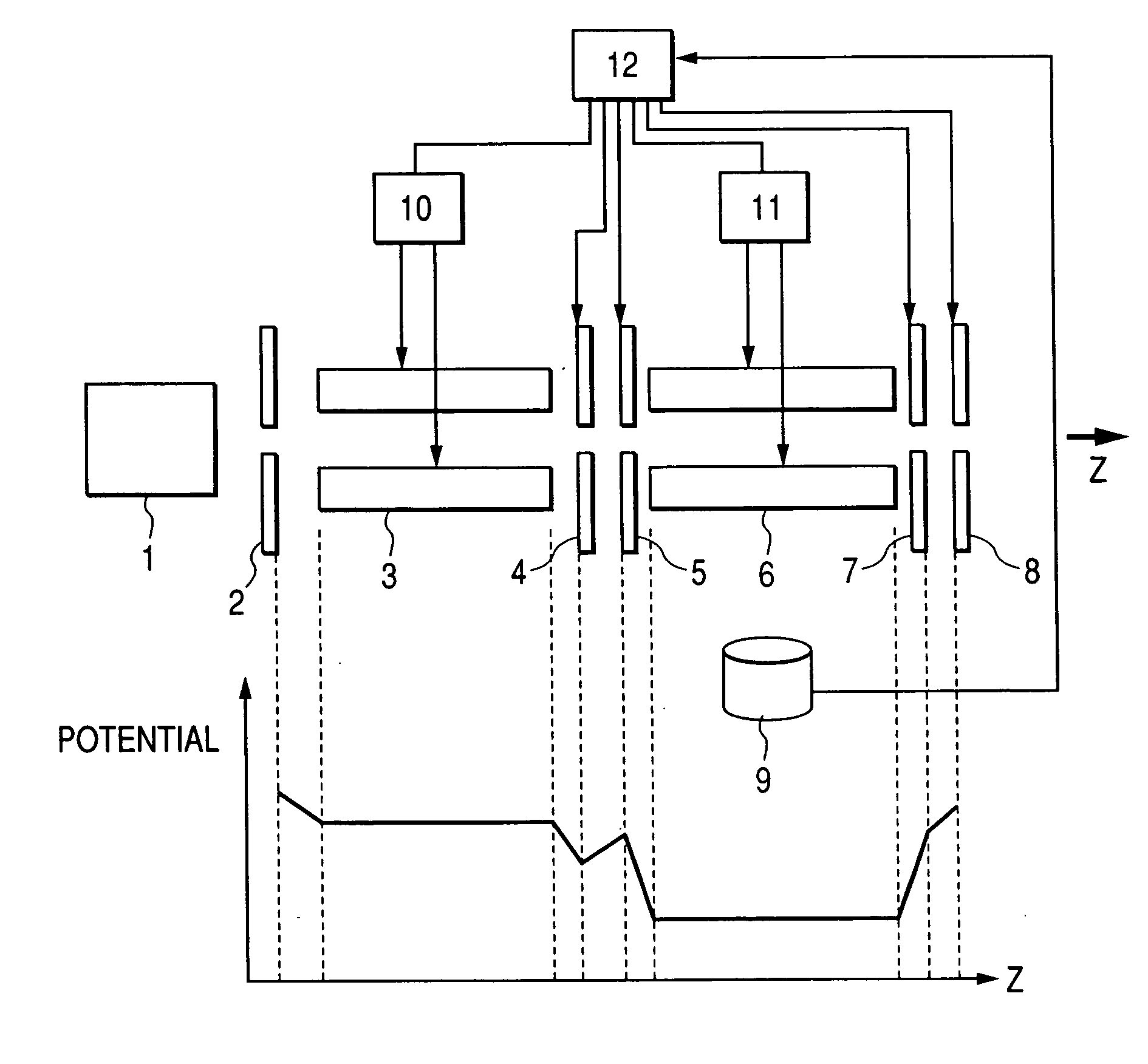
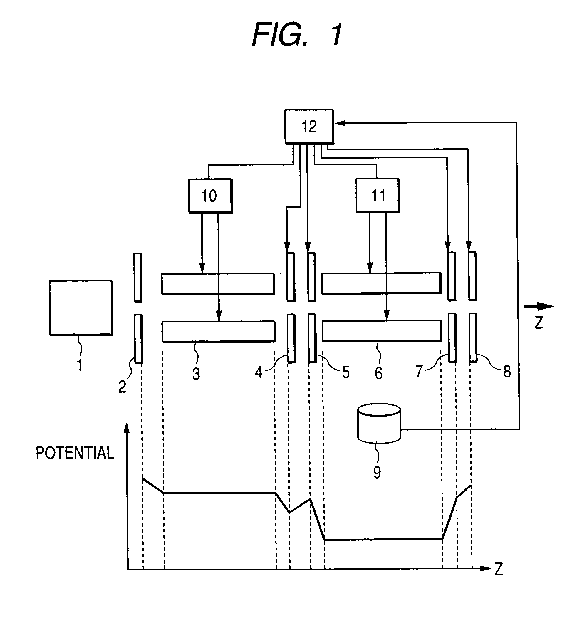
[0038]FIG. 1 is a view showing a constitutional example of a linear ion trap mass spectrometer of Example 1 according to the present invention. FIG. 1 shows, in the lower part, a potential for each of portions of a quadrupole mass filter and a linear ion trap near the center axis for z axis.

[0039] In FIG. 1, as an ion source 1 for ionizing a specimen to generate ions, one of ion sources of an electro spray ion source, an atmospheric pressure chemical ion source, an atmospheric pressure photo-ion source, or an atmospheric pressure matrix assisted laser desorption ion source is used. Ions generated from the specimen in the ion source 1 are passed through a not illustrated differential pumping region and an orifice 2 and introduced to a quadrupole mass filter comprising quadrupole rods 3.

[0040] An RF voltage at 1 MHz of about several tens V to several kV at the reversed phase is applied alternately to each of the quadrupole rods 3, and a DC voltage of several tens V to several kV is ...

example 2

[0070]FIG. 7 is a view showing a constitutional example of a linear ion trap mass spectrometer in Example 2 according to the invention. FIG. 7 shows, in the lower part, the potential for each of portions near the center axis of z axis of the quadrupole mass filter and the linear ion trap. Example 2 is different in that ions are mass selectively ejected in the axial direction with respect to example 1. Accordingly, the voltage on the ion stop lens 8 is set lower than the potential on the linear ion trap end lens.

[0071] As a buffer gas, inert He, Ar, N2, etc. are used and the pressure inside the linear ion trap is kept about at 10−2 Torr to 10−4 Torr for He, and about at 3×10⁻³ Torr to 3×10⁻⁵ Torr for Ar, and N2. Ions are cooled by collision with the buffer gas and converged on the center axis of the linear ion trap.

[0072] A DC bias at about 3V to 5V relative to the DC bias on the linear ion trap rod 6 is applied to the linear ion trap inlet lens 5 and the linear ion trap end lens 7...

example 3

[0076]FIG. 8 is a view showing a constitutional example of a linear ion trap mass spectrometer in Example 3 according to the invention. FIG. 8 shows, in the lower part, the potential for each of portions near the center axis of z axis of the quadrupole mass filter and the linear ion trap. An inserted lens 16 is inserted and a DC bias is applied to the linear ion trap rod 15, whereby a harmonic potential can be formed on the axis.

[0077] Example 3 has the constitution in which linear ion trap rods 15 are disposed instead of the linear ion trap rods 6 of Example 2 shown in FIG. 7 and the inserted lens 16 is interposed between the linear ion trap rods 15, and a linear ion trap power source 13 for supplying voltage to the linear ion trap rods 15 and a inserted lens power supply 14 for supplying voltage to the inserted lens 16 are disposed. The constitution of introducing the buffer gas into the region where the linear ion trap rods 15 are disposed and the pressure condition inside the l...


PUM


Abstract

A mass spectrometer using a linear ion trap capable of efficiently suppressing the space charge and enabling scanning for a wide m/z range at a high Duty Cycle is provided. The mass spectrometer comprises: an ion source for ionizing a specimen to generate ions, an ion transport portion for transporting the ions, a linear ion trap portion for accumulating the transported ions by a potential formed axially, and a control portion of ejecting the ions within a second m/z range different from a first m/z range from the linear ion trap portion substantially at the same timing as the timing of accumulating the ions within the first m/z range to the linear ion trap portion, in which the control portion conducts control of ejecting the ions mass selectively from the linear ion trap portion by any of voltage application of (1) applying a supplemental AC voltage between at least a pair of linear ion trap rods constituting the linear ion trap portion, (2) applying a supplemental AC voltage to an end lens constituting the linear ion trap portion, and (3) applying a supplemental AC voltage between inserted lenses, the inserted lenses constituting the linear ion trap portion. The ion transportation portion having a mass selection means for selecting the ions in the first m/z range.

Description

CLAIM OF PRIORITY [0001] The present invention claims priority from Japanese application JP 2004-169749 filed on Jun. 8, 2004, the content of which is hereby incorporated by reference to this application. BACKGROUND OF THE INVENTION [0002] The present invention concerns a mass spectrometer. [0003] In the following description, mass or m / z means a mass to charge ratio, and a mass range or a m / z range means a range for the mass to charge ratio. [0004] In the linear ion trap mass spectrometer used for proteome analysis, etc., high sensitivity, high mass accuracy, MSn analysis, etc. are required. Mass spectrometry using the linear ion trap in the prior art is to be described. [0005] In the prior art described, for instance, in U.S. Pat. No. 5,420,425 (Patent Document 1), after accumulation of ions introduced into an linear ion trap, ion selection or ion dissociation is conducted as required. Then, ions are ejected mass selectively from the linear ion trap in the radial direction by scan...

Claims


Application Information

Patent Timeline
IPC IPC(8): G01N27/62H01J49/06H01J49/16H01J49/40H01J49/42
CPCH01J49/4225H01J49/004H01J49/4265
Inventor HASHIMOTO, YUICHIROHASEGAWA, HIDEKIBABA, TAKASHISATAKE, HIROYUKIWAKI, IZUMI
Owner HITACHI HIGH-TECH CORP
Why Eureka
Try Eureka