Transceive surface coil array for magnetic resonance imaging and spectroscopy

a magnetic resonance imaging and spectroscopy technology, applied in the field of magnetic resonance imaging (mri), can solve the problems of increasing local and global specific absorption rate, increasing radiation loss, and less effective high field regime, and achieving the effects of reducing image artefacts, reducing radiation loss, and reducing radiation loss

Inactive Publication Date: 2005-12-15
THE JOHN P ROBARTS RES INST
View PDF9 Cites 35 Cited by
  • Summary
  • Abstract
  • Description
  • Claims
  • Application Information

AI Technical Summary

Benefits of technology

[0033] The surface coil array is advantageous in that it provides the flexibility of using a single array for transmitting and / or receiving RF signals, which has benefits in fast parallel imaging techniques and limits image artefacts associated with using separate transmit and receive coil arrays. The surface coil array is also less SAR limited at high field strengths due to the proximity of the surface coil array to the imaging volume, thereby limiting electric field losses. Further, the surface coil array can be tuned for a variety of paramagnetic nuclei (e.g. 13C, 1H, 23Na, 31P, etc. . .) for use in many MR imaging and spectroscopy applications.
[0034] The surface coil array provides for the ability to vary surface coil size and geometry thereby offering great flexibility in custom imaging applications (e.g. whole body imaging (TIM)). As the surface coil array can be used with multiple, more economical lower power amplifiers for transmit applications, more control in imaging sequences is available. Also, the surface coil array provides for use with conventional 50Ω transmit and receive components while maintaining isolation between surface coils.

Problems solved by technology

Although these volume coils operate well at low magnetic field strengths, they become less effective in the high field regime i.e. at magnetic field strengths greater than 3 T. As the static magnetic field strength used in MRI increases, the wavelength of the associated Larmor RF approaches the dimensions of the volume coil and volume of interest (VOI).
Several imaging problems arise in this full wavelength regime namely, increased radiation losses, increased local and global specific absorption rate (SAR), and dielectric resonance effects that create both inhomogeneous images and signal loss.
The predominant impediment to surface coil array design is however, the strong magnetic coil-to-coil coupling.
Unfortunately, the resultant overlapping sensitivity profiles are less than ideal for fast parallel imaging techniques, which are more effective when sensitivity profiles of individual surface coils do not overlap.
Unfortunately, low (or high) impedance preamplifiers are not generally available off-the-shelf and are therefore, more complex, expensive and time consuming to implement.
Furthermore, low input impedance RF power amplifiers are not widely commercially available off-the-shelf, thereby practically limiting this coil-to-coil magnetic coupling reduction technique to receive-only applications.
However, considerable electric field loss and strong coupling between lattice networks limits their application at higher field strengths.
Unfortunately, this design requires a common ground resulting in electric field losses and requires a common connection between all of the coils, which is geometrically restrictive.
Unfortunately, this ladder network is complex and appears to be limited to low field MRI applications, as considerable electric field losses, and strong coupling between lattice networks would limit its application at high field strengths.

Method used


Image

  • Transceive surface coil array for magnetic resonance imaging and spectroscopy
  • Transceive surface coil array for magnetic resonance imaging and spectroscopy
  • Transceive surface coil array for magnetic resonance imaging and spectroscopy

Examples


Embodiment Construction

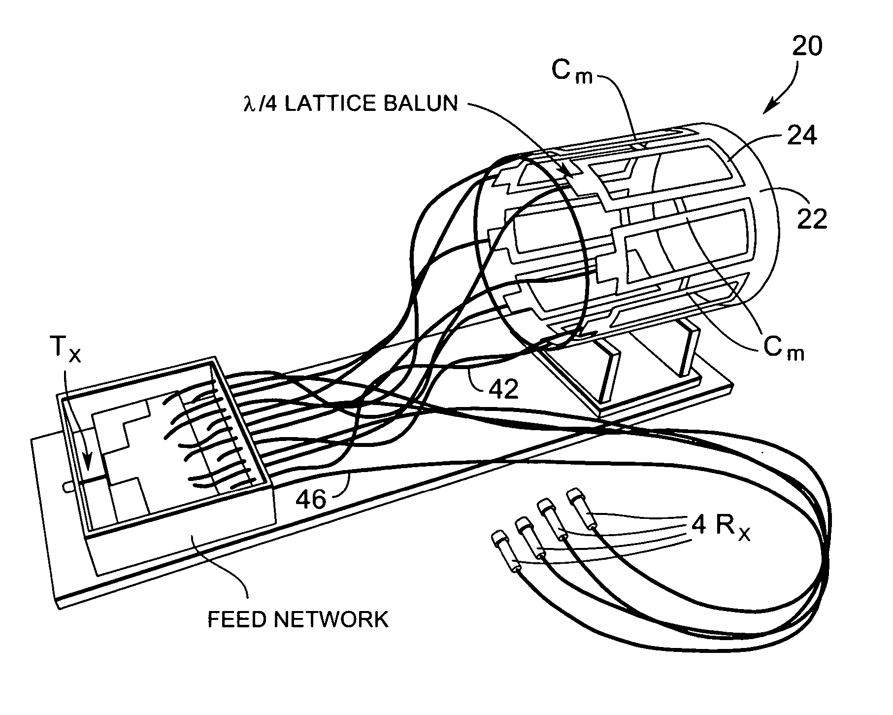
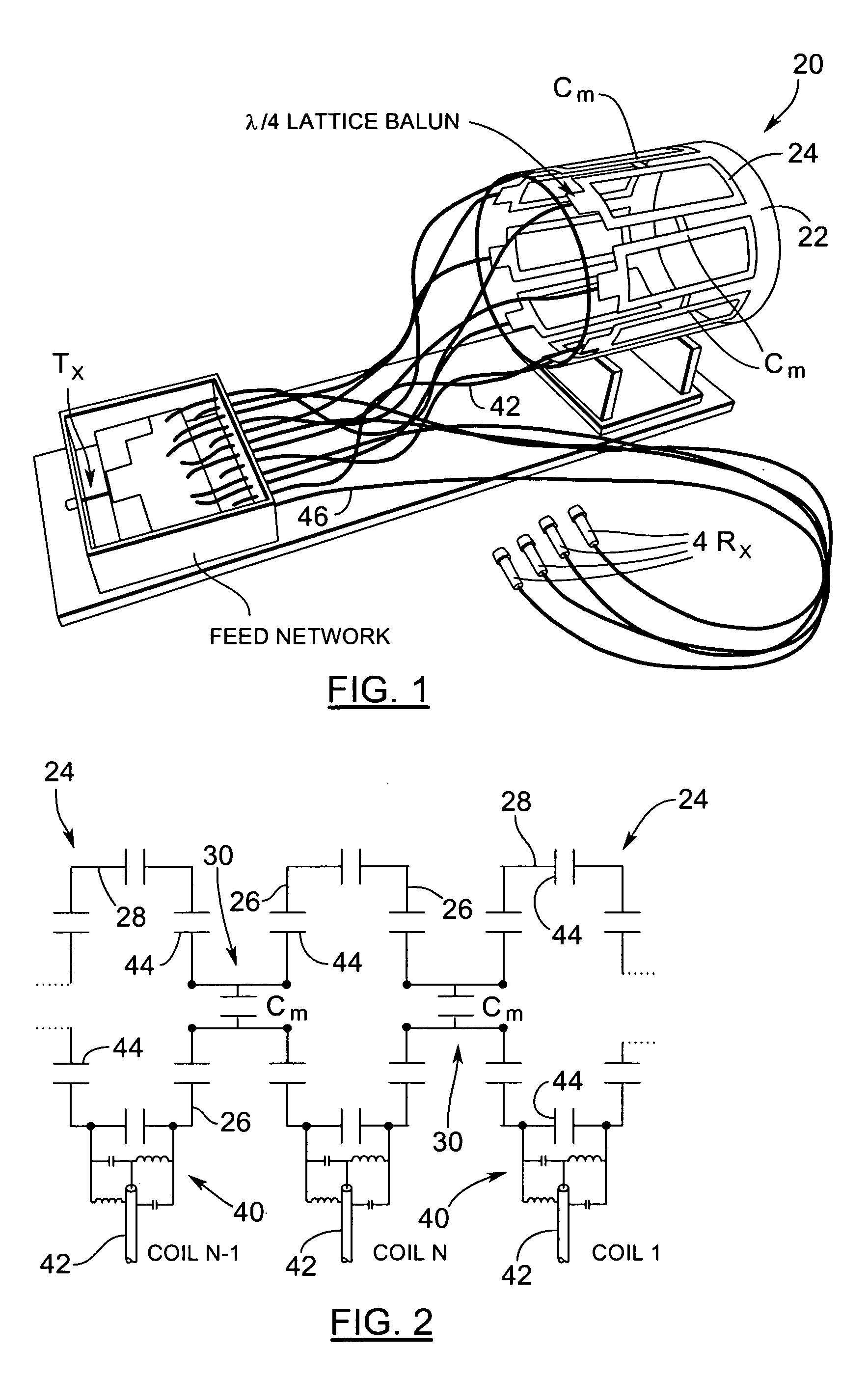
[0046] Turning now to FIGS. 1 and 2, a transceive surface coil (TSC) array for magnetic resonance imaging and spectroscopy is shown and is generally identified by reference numeral 20. As can be seen, TSC array 20 comprises a cylindrical supporting shell 22 on which are mounted a plurality of generally equally spaced, rectangular surface coils 24. The shell 22 is formed of acrylic and has inside and outside diameters of approximately 24.1 cm and 25.4 cm respectively. In this particular example, the TSC array includes eight (8) surface coils 24. Each of the surface coils 24 is substantially identical and is constructed of conductive strips, in this case copper tape, having a thickness equal to approximately 50 μm. Each surface coil 24 includes two legs 26 having a length of approximately 21 cm and two legs 28 having a length of approximately 8.1 cm. The width of each leg is approximately 63.5 mm and the inter-surface coil spacing is approximately 2 cm.

[0047] A magnetic decoupling ci...


PUM


Abstract

A surface coil array comprises a surface coil support and an arrangement of non-overlapping magnetically decoupled surface coils mounted on the support. The surface coils encompass a volume into which a target to be imaged is placed. Magnetic decoupling circuits act between adjacent surface coils. Impedance matching circuitry couples the surface coils to conventional transmit and receive components.

Description

CROSS-REFERENCE TO RELATED APPLICATIONS [0001] This application claims the benefit of U.S. Provisional Patent Application No. 60 / 554,350 filed on Mar. 19, 2004 for an invention entitled “Transceive Surface Coil Array For Magnetic Resonance Imaging and Spectroscopy”.FIELD OF THE INVENTION [0002] The present invention relates generally to magnetic resonance imaging (MRI) and more specifically, to a transceive surface coil array for magnetic resonance imaging and spectroscopy. BACKGROUND OF THE INVENTION [0003] Nuclear Magnetic Resonance (NMR) Imaging, or Magnetic Resonance Imaging (MRI) as it is commonly known, is a non-invasive imaging modality that can produce high resolution, high contrast images of the interior of the human body. MRI involves the interrogation of the nuclear magnetic moments of a subject placed in a strong magnetic field with radio frequency (RF) magnetic fields. A MRI system typically comprises a fixed magnet to create the main strong magnetic field, a gradient c...

Claims


Application Information

Patent Timeline
Patent Type & Authority Applications(United States)
IPC IPC(8): G01R33/34G01R33/3415G01R33/36G01V3/00
CPCG01R33/34046G01R33/3415G01R33/365
Inventor PINKERTON, ROBERT G.MENON, RAVI S.
Owner THE JOHN P ROBARTS RES INST
Why Eureka
Try Eureka