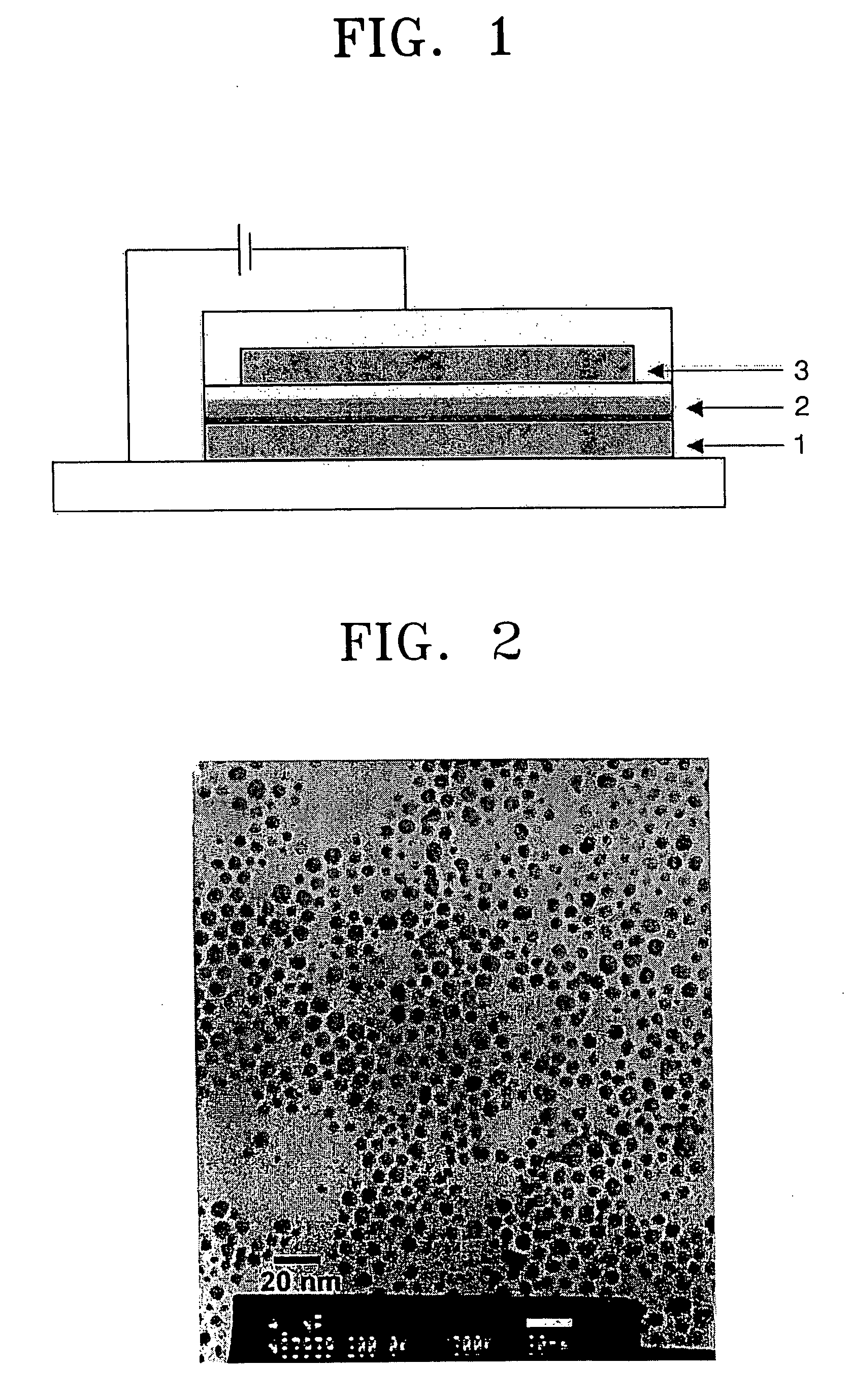
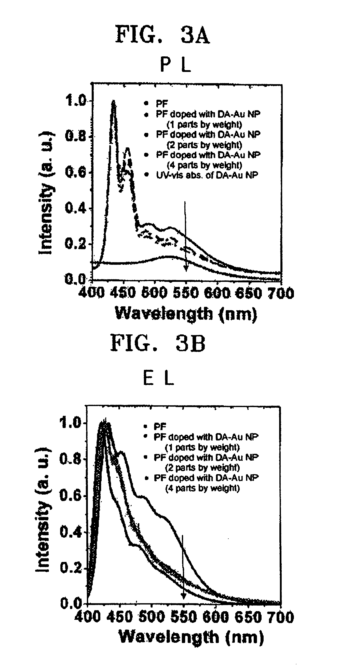
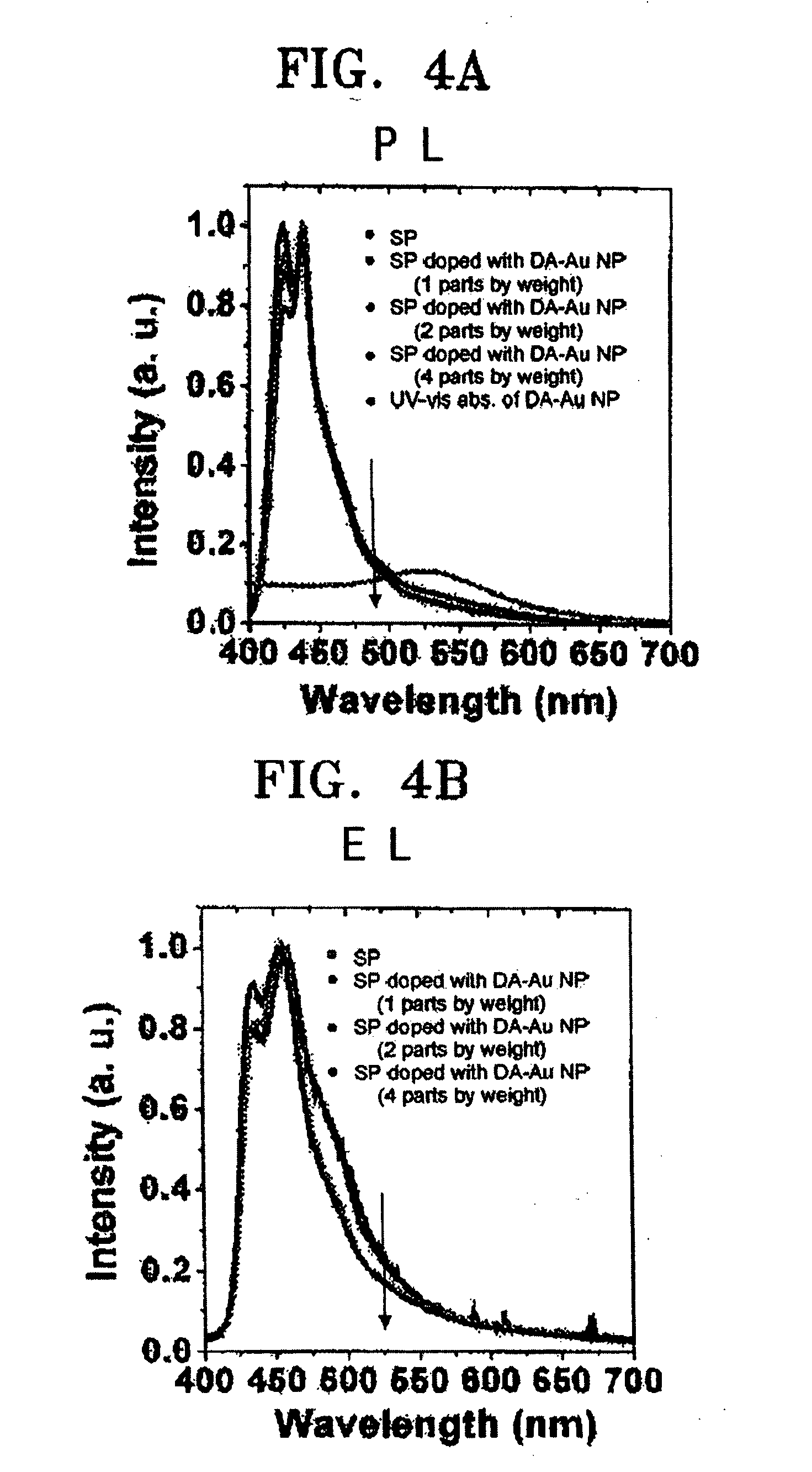
Electroluminescent device using metal nanoparticles
a metal nanoparticle and electroluminescent technology, applied in the field of electroluminescent devices using metal nanoparticles, can solve the problems of unsatisfactory color purity characteristics, unsatisfactory blue emission efficiency and color purity when used in organic el devices, and achieve the effect of improving color purity and emission efficiency
- Summary
- Abstract
- Description
- Claims
- Application Information
AI Technical Summary
Benefits of technology
Problems solved by technology
Method used
Image
Examples
example 1
Synthesis of Polyfluorene
(a) Synthesis of 9,9′-dioctyl-2,7-dibromofluorene monomer
[0047]
[0048] 25 g (77 mmol) of 2,7-dibromofluorene and 36 g (185 mmol) of octylbromide were dissolved in 100 ml of toluene and 1.25 g (3.85 mmol) of tetrabutylammonium bromide was then added thereto. Then, a sodium hydroxide aqueous solution obtained by dissolving 31 g (770 mmol) of sodium hydroxide in 50 ml water was added to the reaction mixture and maintained for one day.
[0049] After the reaction was terminated, the resultant solution was extracted with water:chloroform (2:1 volumetric ratio). An obtained organic layer was dried over magnesium sulfate (MgSO4) and concentrated. A concentrate was purified by column chromatography using n-hexane as an eluent and distilled under a reduced pressure to remove an octylbromide residue. As a result, 40 g (yield 95%) of 9,9′-dioctyl-2,7-dibromofluorene was obtained. The structure of the 9,9′-dioctyl-2,7-dibromofluorene was identified by 1H-NMR spectrum.
(b...
example 2
Synthesis of Polyspirobifluorene
(a) Synthesis of Monomer
(a-1) Synthesis of Compound (B)
[0051]
[0052] The compound (A) was obtained from 2-bromo-4,5-di(2-ethylhexyloxy)biphenyl.
[0053] The compound (A) in 50 ml ether was added to a solution of 3.36 g (10 mmol) of 2,7-dibromo-9-fluorenone in 50 ml ether and stirred under reflux overnight.
[0054] After the reaction was terminated, the resultant solution was cooled, and the yellow solid powders were filtered and three times washed with ether. Then, the resultant product was added to ammonium chloride and stirred for 10 hours. The precipitate was filtered, three times washed with water, and recrystallized with ethanol to obtain the compound (B) of a yellow solid (yield 83%).
(a-2) Synthesis of Compound (C)
[0055] 5.0 g (5 mmol) of the compound (B) was added to 15 ml of CH3COOH and gently refluxed. 0.5 ml of hydrochloric acid was then added to the reaction mixture and refluxed for one hour.
[0056] After the reaction was terminated, the ...
example 3
Preparation of Dodecylamine-Coated Gold Nanoparticles (DA-Au NPs)
[0058] 112 mg (0.284 mmol) of HAuCl4.3H2O was dissolved in 25 ml of distilled water and rapidly stirred. A solution of 0.389 g (0.71 mmol, 2.5 equivalents) of N(C8H17)4Br in 25 ml of toluene was then added and continuously stirred until an orange color disappeared. When the reaction mixture turned colorless, a solution of 0.574 g (3.10 mmol) of dodecylamine in 25 ml of toluene was added to the reaction mixture with rapidly stirring. After adding the solution of dodecylamine, a dark beige precipitate was created in the reaction mixture, and then the resulting solution was stirred for 10 minutes. Then, a solution of 0.165 g (4.36 mmol) of NaBH4 in 25 ml of distilled water was added and vigorously stirred at room temperature in an atmosphere condition for 12 hours.
[0059] After the reaction was terminated, an aqueous layer was discarded and a toluene layer was distilled under a reduced pressure to a concentration of 5 ml...
PUM
| Property | Measurement | Unit |
|---|---|---|
| Fraction | aaaaa | aaaaa |
| Percent by mass | aaaaa | aaaaa |
| Thickness | aaaaa | aaaaa |
Abstract
Description
Claims
Application Information
 - R&D
- Intellectual Property
- Life Sciences
- Materials
- Tech Scout
- Unparalleled Data Quality
- Higher Quality Content
- 60% Fewer Hallucinations
Browse by: Latest US Patents, China's latest patents, Technical Efficacy Thesaurus, Application Domain, Technology Topic, Popular Technical Reports.
© 2025 PatSnap. All rights reserved.Legal|Privacy policy|Modern Slavery Act Transparency Statement|Sitemap|About US| Contact US: help@patsnap.com


