Phosphor sheet manufacturing apparatus

a technology of phosphor sheet and manufacturing apparatus, which is applied in the direction of vacuum evaporation coating, chemical vapor deposition coating, coating, etc., can solve the problems of deterioration in image quality, blurring of read image, and large error factor in the film thickness distribution of phosphor sheet, so as to achieve satisfactory film thickness distribution and high uniformity. , the effect of high uniformity

Inactive Publication Date: 2005-12-22
FUJIFILM HLDG CORP +1
View PDF12 Cites 7 Cited by
  • Summary
  • Abstract
  • Description
  • Claims
  • Application Information

AI Technical Summary

Benefits of technology

[0021] In the phosphor sheet manufacturing apparatus according to the first aspect of the present invention, in manufacturing a phosphor sheet through formation of a phosphor layer (a layer made of a stimulable phosphor) by vacuum evaporation, a substrate is conveyed linearly (preferably repeatedly moved in a to-and-fro manner), and evaporation sources for film forming materials are arranged linearly in a direction perpendicular to the direction in which the substrate is conveyed, thereby forming the phosphor layer. As a result, the entire substrate surface can be exposed to the vapor of the film forming materials with very high uniformity, which makes it possible to manufacture a phosphor sheet exhibiting a very satisfactory film thickness distribution of ±3% or less. Further, it is desirable for the formation of the phosphor layer through vacuum evaporation to be effected by a multi-source vacuum evaporation method in which a phosphor component constituting the base material and an activator component which is a minute-amount component are put in separate evaporation sources. In accordance with the present invention in which the substrate is conveyed linearly and the evaporation sources are arranged in a direction perpendicular to the direction in which the substrate is conveyed, it is possible to disperse the activator component in the phosphor layer with high uniformity in both the planar direction and thickness direction of the phosphor layer. Thus, it is possible to obtain a phosphor sheet superior in photostimulated luminescence characteristics and uniformity in sensitivity, etc.
[0022] According to the second aspect of the present invention, there is provided a phosphor sheet manufacturing apparatus which includes means for heating film forming materials by resistance heating and a gas introducing nozzle for introducing an inert gas into a vacuum chamber (film formation system), and in which a phosphor layer is formed through vacuum evaporation while conveying a substrate linearly (preferably while moving the substrate in a to-and-fro manner). Thus, it is possible to form a phosphor layer having excellent crystallinity and exhibiting a highly uniform film thickness distribution of 3% or less, and to facilitate the position setting for the evaporation sources.

Problems solved by technology

That is, when the photostimulated luminescence is not focused on the line sensor, a problem occurs, such as blurring of the read image.
In particular, for medical use as in the case of the FCR mentioned above, such deterioration in image quality may lead to a serious problem, such as a discrepancy in diagnosis result or a wrong diagnosis.
Thus, when the size of the gap between them is taken into account, the film thickness distribution of the phosphor sheet constitutes a great error factor for the gap between the line sensor and the phosphor sheet.
While it helps achieve a reduction in film thickness distribution of a phosphor layer formed by vacuum evaporation, this method requires a high-speed substrate rotating means, resulting in a rather high apparatus cost.
Further, since the substrate is rotated at high speed, it is necessary to perform maintenance frequently, resulting in a rather high running cost.
However, in the vacuum evaporation conducted while rotating the substrate, the setting of the position of the evaporation source is very difficult to perform.
In particular, when resistance heating is adopted, even a slight inadequacy in the position setting of the evaporation source may lead to the case where a phosphor layer whose uniformity in film thickness distribution is ±3% or less cannot be formed in a consistent manner.

Method used


Image

  • Phosphor sheet manufacturing apparatus
  • Phosphor sheet manufacturing apparatus
  • Phosphor sheet manufacturing apparatus

Examples


example

[0137] In the following, the present invention will be described in more detail with reference to a specific example thereof.

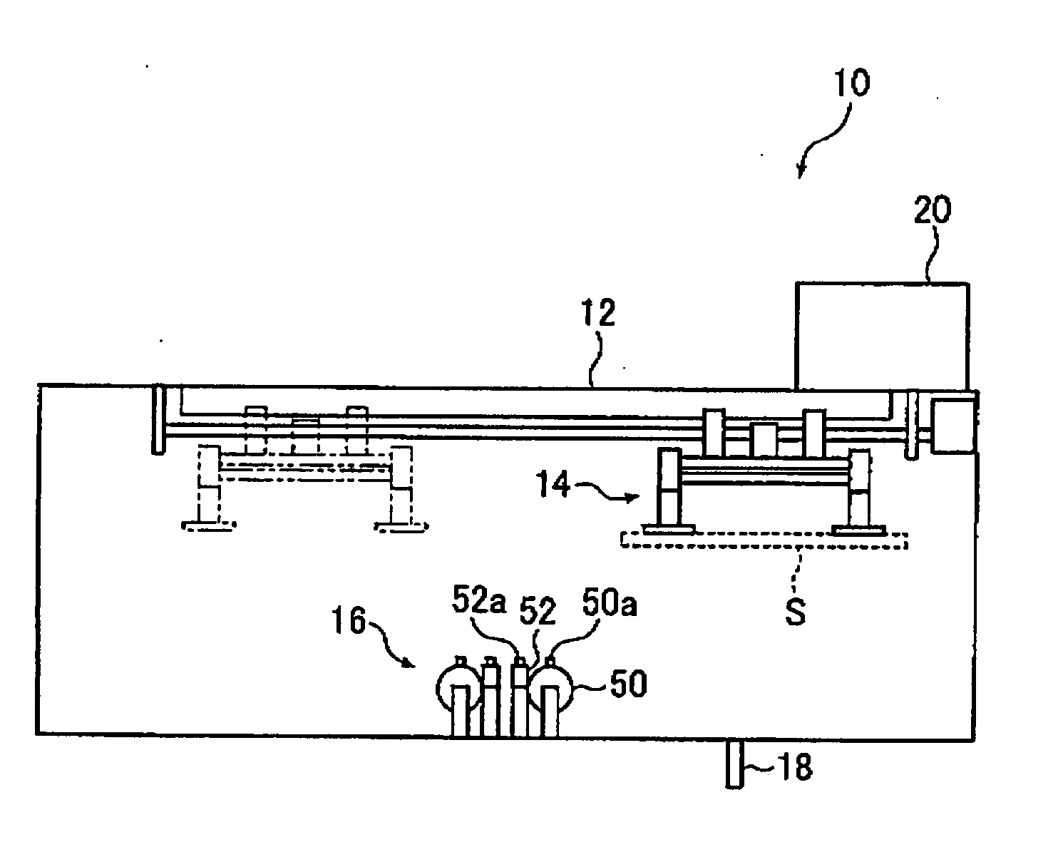
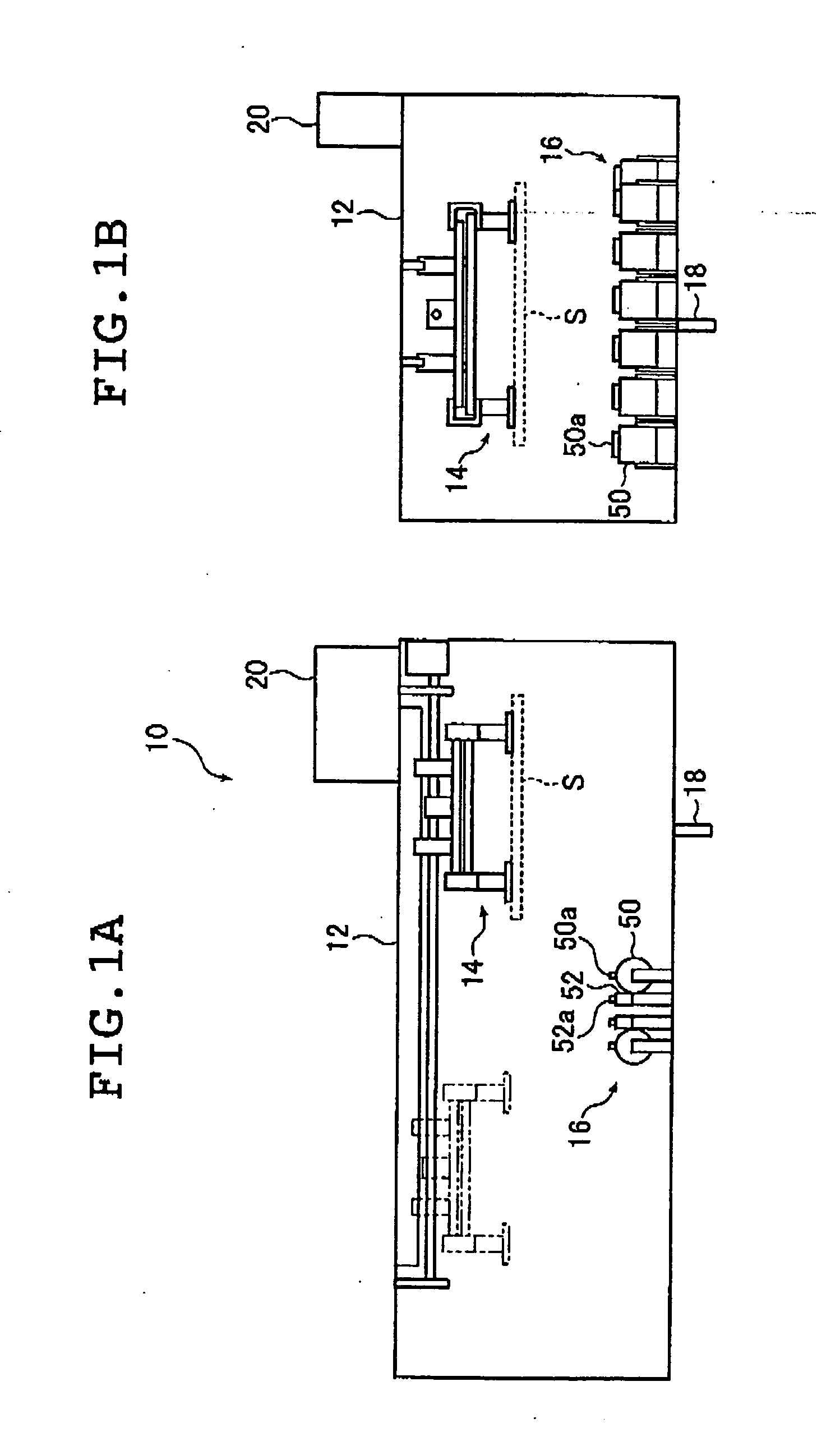
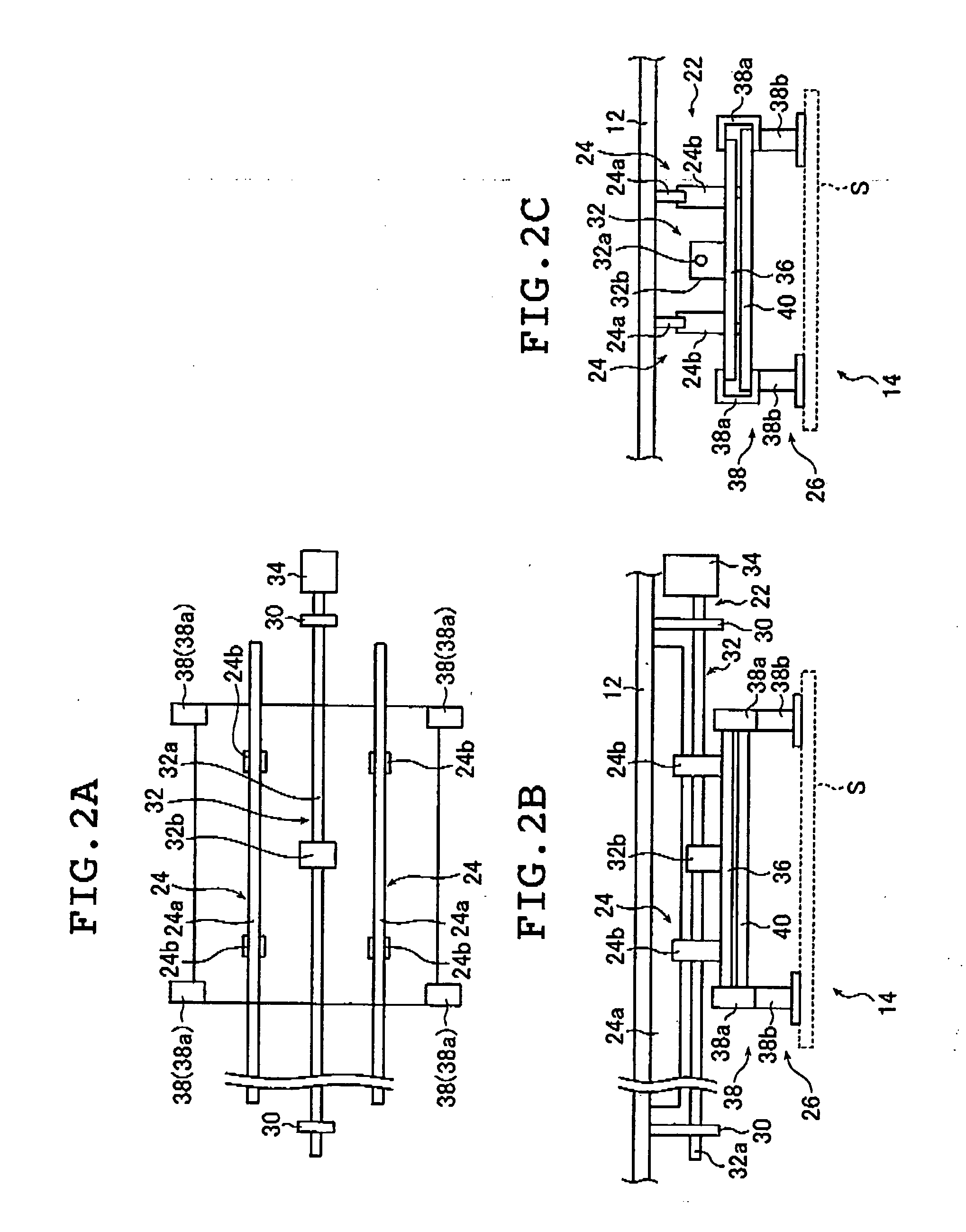
[0138] First, the vacuum chamber 12 was opened, and an aluminum substrate S of 450×450 mm and with a thickness of 10 mm was secured to the retaining mechanism 38b of the retaining means 26; further, all the crucibles 50 were filled with cesium bromide (CsBr) and all the crucibles 52 were filled with europium bromide (EuBrx, where x is approximately 2) to predetermined amounts. Then, the shutter was closed, and further, the vacuum chamber 12 was closed.

[0139] After the vacuum chamber 12 was closed, the vacuum evacuating means was driven to start the evacuation of the vacuum chamber 12. When the internal pressure of the vacuum chamber 12 reaches 8×10⁻⁴ Pa, argon gas was introduced into the vacuum chamber 12 through the gas introducing nozzle 18 while continuing the evacuation to thereby adjust the internal pressure of the vacuum chamber 12 to 1 Pa. Further, th...


PUM

PropertyMeasurementUnit
internal pressureaaaaaaaaaa
thicknessaaaaaaaaaa
thicknessaaaaaaaaaa

Abstract

There is provided a stimulable phosphor sheet manufacturing apparatus which forms a stimulable phosphor layer through vacuum evaporation in a vacuum chamber. A substrate is conveyed linearly, evaporation sources are arranged in a direction perpendicular to a direction in which the substrate is conveyed, and/or the apparatus includes the evaporation sources relying on resistance heating and a gas introducing nozzle for introducing an inert gas into a vacuum chamber during film formation. A phosphor layer of highly uniform film thickness distribution can be formed.

Description

[0001] This application claims priority on Japanese patent applications No.2004-172708 and No. 2004-172868, the entire contents of which are hereby incorporated by reference. In addition, the entire contents of literatures cited in this specification are incorporated by reference. In addition, the entire contents of literatures cited in this specification are incorporated by reference. BACKGROUND OF THE INVENTION [0002] The present invention relates to an apparatus for manufacturing a stimulable phosphor sheet for use in radiation image recording (photographing) in computed radiography (CR) or the like. More specifically, the present invention relates to a phosphor sheet manufacturing apparatus that forms a layer made of a stimulable phosphor on the surface of a substrate by vacuum evaporation. [0003] There are known a class of phosphors which accumulate a portion of applied radiations (e.g. x-rays, α-rays, β-rays, γ-rays, electron beams, and uv (ultraviolet) radiation) and which, u...

Claims


Application Information

Patent Timeline
Patent Type & Authority Applications(United States)
IPC IPC(8): C23C14/06C23C14/24C23C14/50C23C14/54C23C16/00
CPCC23C14/0694C23C14/546C23C14/50C23C14/24
Inventor KASHIWAYA, MAKOTONAKADA, JUNJINOGUCHI, YUKIHISA
Owner FUJIFILM HLDG CORP
Why Eureka
Try Eureka