Hydrogen generation apparatus and method for using same

a hydrogen generation and apparatus technology, applied in the field of chemical arts, can solve the problems of insufficient energy storage capacity of electrochemical generators, inability to meet the needs of certain applications, and inability to provide compressed hydrogen. , the safety of hydrogen handling and storage is affected

Inactive Publication Date: 2005-12-22
INTELLIGENT ENERGY INC
View PDF16 Cites 37 Cited by
  • Summary
  • Abstract
  • Description
  • Claims
  • Application Information

AI Technical Summary

Benefits of technology

[0031] Also in accordance with the invention there has been found a method for generating hydrogen. In a first step a hydrogen-producing fuel is flowed through the reaction zone and into the combustion chamber of the hydrogen membrane reactor. The reaction zone contains a reaction catalyst initially at a temperature less than the reaction catalyst's light-off temperature. In preferred embodiments, the light off temperature of the reaction catalyst is less than 650° C. Suitable reaction catalysts inc

Problems solved by technology

However, the amount of energy that can be stored in storage or rechargeable batteries is insufficient to meet the need of certain applications.
Merely providing compressed hydrogen is not always a viable option, because of the substantial volume that even a highly compressed gas occupies.
Furthermore, there are safety issues involved with the handling and storage of hydrogen in the compressed gas form or in the liquid form.
Hydrocarbon fuels are somewhat more technically challenging, because hydrocarbon reformation requires relatively higher temperatures, and the simple cracking of hydrocarbons produces a solid residue which is undesirable in a fuel cell application.
It is a drawback of ammonia decompos

Method used


Image

  • Hydrogen generation apparatus and method for using same
  • Hydrogen generation apparatus and method for using same
  • Hydrogen generation apparatus and method for using same

Examples


Embodiment Construction

[0084] Particular embodiments of the invention are described below in considerable detail for the purpose for illustrating its principles and operation. However, various modifications may be made, and the scope of the invention is not limited to the exemplary embodiments described.

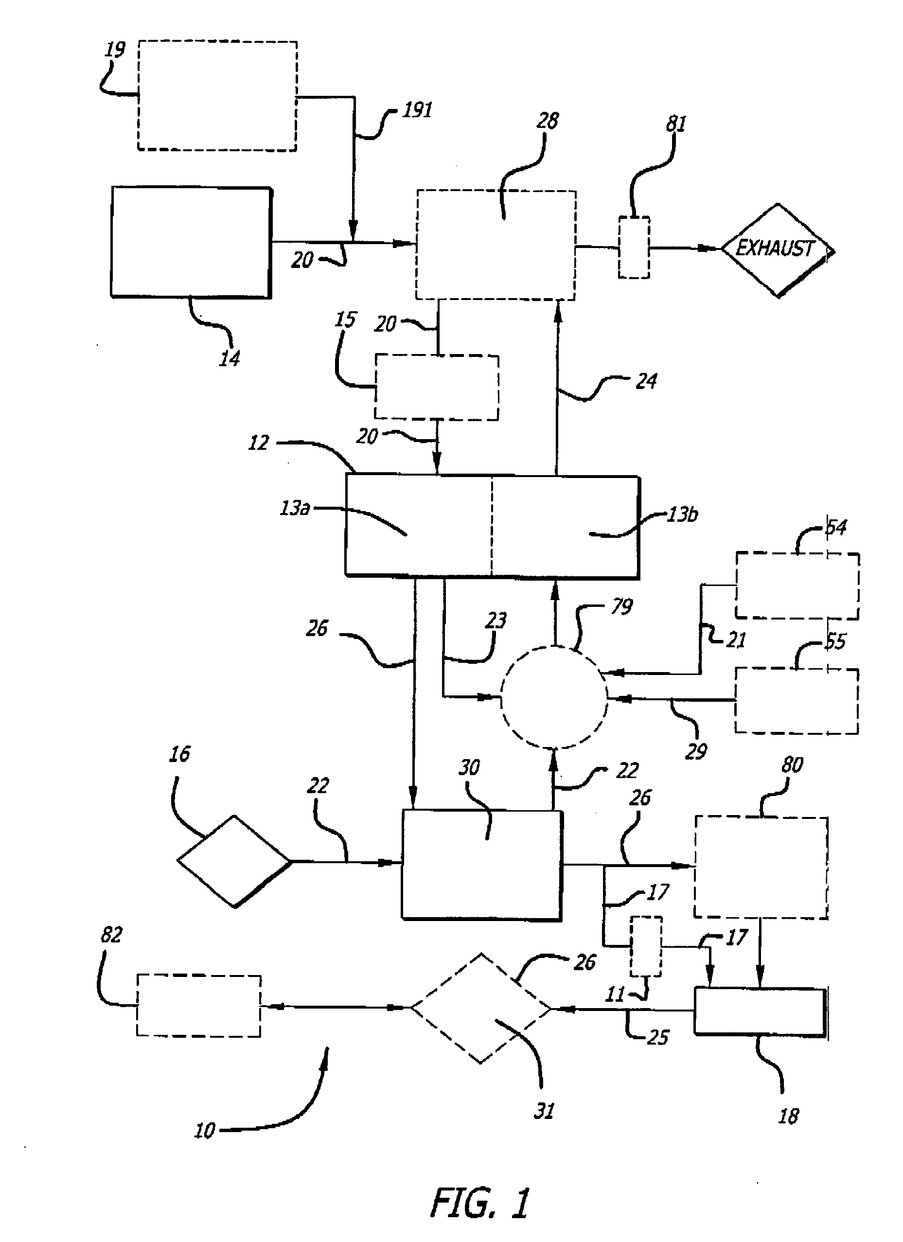
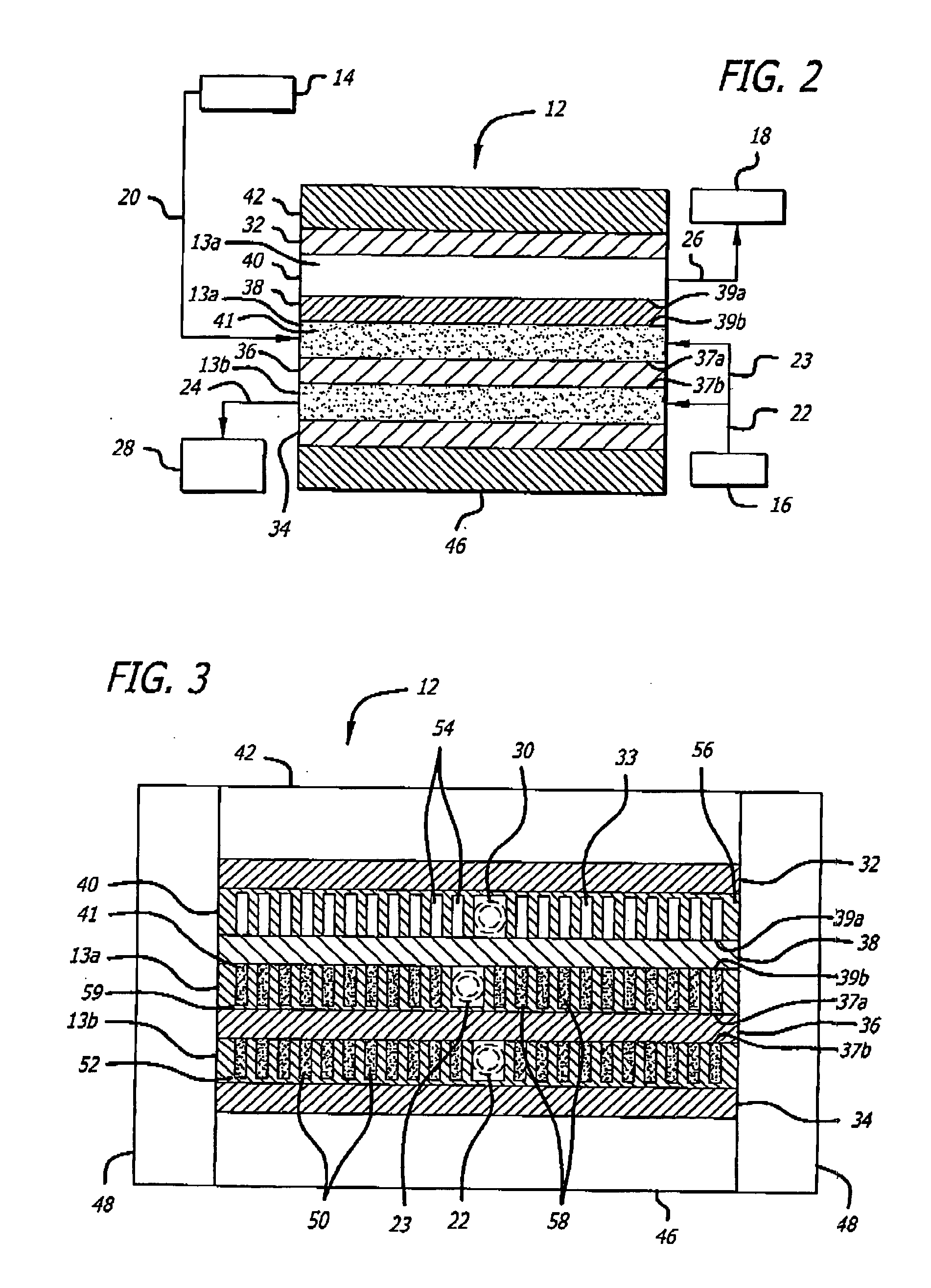
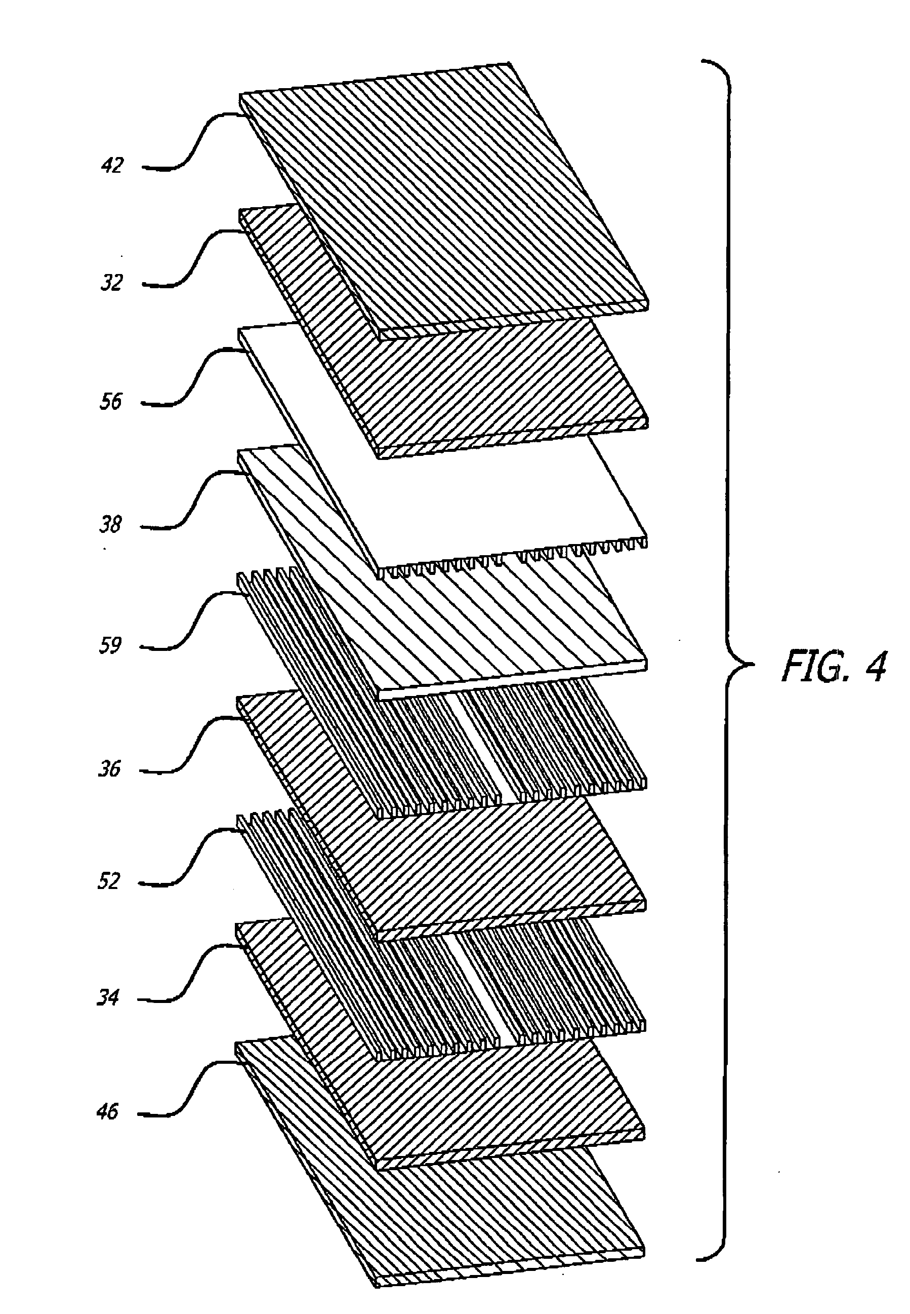
[0085] The hydrogen generators in accordance with the invention include a reaction chamber and a combustion chamber. In the reaction chamber hydrogen is produced from a fuel. In the combustion chamber thermal energy is produced by combustion of a fuel, wherein the thermal energy produced is to be supplied to the reaction chamber. Accordingly, the reaction chamber and the combustion chamber are in a heat exchange relationship.

[0086] The fuel to be supplied to the reaction chamber include a wide variety of chemically different fuel, such as hydrocarbons and ammonia.

[0087] It is an advantage of the hydrogen generators in accordance with the invention, that with only minor modifications they can be used to ...


PUM


Abstract

A compact hydrogen generator for use with fuel cells and other applications includes a hydrogen membrane reactor having a combustion chamber and a reaction chamber. The two chambers are have a fluid connection and a heat exchange relationship with one another. The hydrogen generation apparatus also includes a fuel supply, a fuel supply line for transporting fuel from the fuel supply to the reaction chamber, an oxygen supply, an oxygen supply line for transporting oxygen form the oxygen supply to the combustion chamber, as well as a tail gas supply line for transporting tail gas supply line for transporting tail gases form the reaction chamber, a combustion by-product line for transporting combustion by-products for the combustion chamber, and a reaction product line for transporting hydrogen from the reaction chamber.

Description

RELATED APPLICATIONS [0001] This application is a continuation-in-part of, and claims priority to U.S. application Ser. No. 10 / 476,015, entitled “HYDROGEN GENERATION APPARATUS AND METHOD FOR USING SAME”, which is a national phase filing of PCT International Application No. PCT / US02 / 12822, filed Apr. 23, 2002 and which claims priority to U.S. Provisional Application No. 60 / 286,114, filed on Apr. 23, 2001, all of which are herein incorporated by referenced in their entirety. This application is also a continuation-in-part and claims priority to U.S. application entitled “Ammonia-Based Hydrogen Generation Apparatus” filed on Apr. 18, 2005 attorney docket number “73358-031110” which is a continuation-in-part of U.S. application Ser. No. 10 / 469,464 filed Aug. 29, 2003, which is a national phase filing of International Application No. PCT / US02 / 06767, filed on Mar. 4, 2002, which claims priority to U.S. Provisional Patent Application No. 60 / 272,806, filed Mar. 2, 2001, all herein incorpora...

Claims


Application Information

Patent Timeline
IPC IPC(8): B01J19/24C01B3/38C01B3/50C07C1/04C10G47/00
CPCB01J19/2475B01J19/249Y02E60/364B01J2208/00203B01J2208/022B01J2219/2453B01J2219/2458B01J2219/2459B01J2219/2462B01J2219/2464B01J2219/2465B01J2219/2466B01J2219/247B01J2219/2475B01J2219/2479B01J2219/2481B01J2219/2482B01J2219/2485B01J2219/2487B01J2219/2497C01B3/384C01B3/501C01B2203/0233C01B2203/041C01B2203/047C01B2203/0475C01B2203/048C01B2203/066C01B2203/0811C01B2203/0822C01B2203/0827C01B2203/0883C01B2203/1223C01B2203/1241C01B2203/1604C07C1/041C07C9/06Y02E60/36Y02P20/10
Inventor CHELLAPPA, ANAND S.POWELL, MICHAEL ROYCALL, CHARLES J.
Owner INTELLIGENT ENERGY INC
Why Eureka
Try Eureka