High-temperature stable gate structure with metallic electrode

a gate structure and high-temperature stable technology, applied in the direction of basic electric elements, electrical equipment, semiconductor devices, etc., can solve the problems of physical vapor deposition methods falling into disfavor, prior forming methods have been unsuccessful in providing uniform, continuous and uniform ultra-thin high-k gate dielectric layers

Inactive Publication Date: 2005-12-22
GLOBALFOUNDRIES INC
View PDF1 Cites 60 Cited by
  • Summary
  • Abstract
  • Description
  • Claims
  • Application Information

AI Technical Summary

Benefits of technology

[0016] It is an object of the present invention to provide a high-k gate dielectric comprising a continuous ultra-thin high-k metal oxide layer having a thickness of about 15 Å or less. Another object of the present invention is to provide a method of forming high-k gate dielectrics comprising a continuous ultra-

Problems solved by technology

For ultra-thin high-k gate dielectric formation, physical vapor deposition methods have fallen into disfavor, as they typically damage the deposition surface during sputtering.
Prior forming methods have been unsuccessful in providing continuous and uniform ultra-thin high-k gate dielectric layers.
Atomic layer deposition (ALD) and chemical vapor deposition (CVD) fail to provide uniform gate dielectric layers, since atomic layer deposition and chemical vapor deposition typically result in non-uniform nucleation when utilized to deposit ultra-thin dielectric layers.
Non-uniform nucleation results from the complex bonding of metal organic or metal halide precursors, which are utilized in CVD and ALD processes.
The complex bonding of metal organic or metal halide precursors acts as an obstruction to full saturation of the deposition surface.
For example, hafnium chloride precursors comprise hafnium bonded with four chlorides, and when the hafnium of the precursor bonds to a silicon-containing surface of a substrate the bonded chlorides can block up to 10 bonding sites of the substrate, resulting in non-uniform nucleation.
Non-continuous dielectric layers incorporated within gate dielectrics typically result in leakage effects, which reduce device performance.
Further, the density of trapped and/or fixed charge can be inadvertently altered by exposure to a high-temperature (e.g., a 1000° C. junction activation anneal) or during FET operation.
Presence of m

Method used


Image

  • High-temperature stable gate structure with metallic electrode
  • High-temperature stable gate structure with metallic electrode
  • High-temperature stable gate structure with metallic electrode

Examples


Embodiment Construction

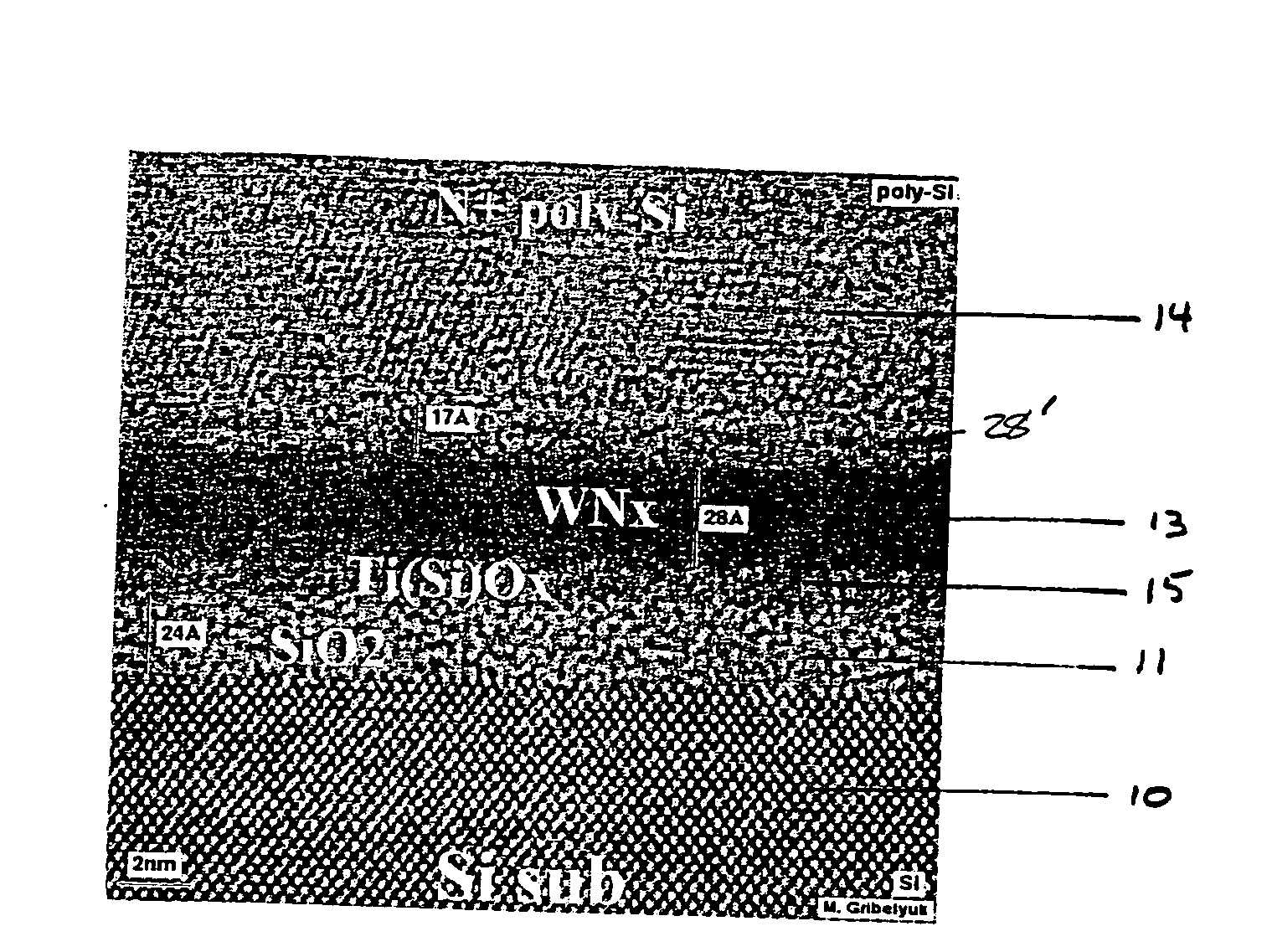
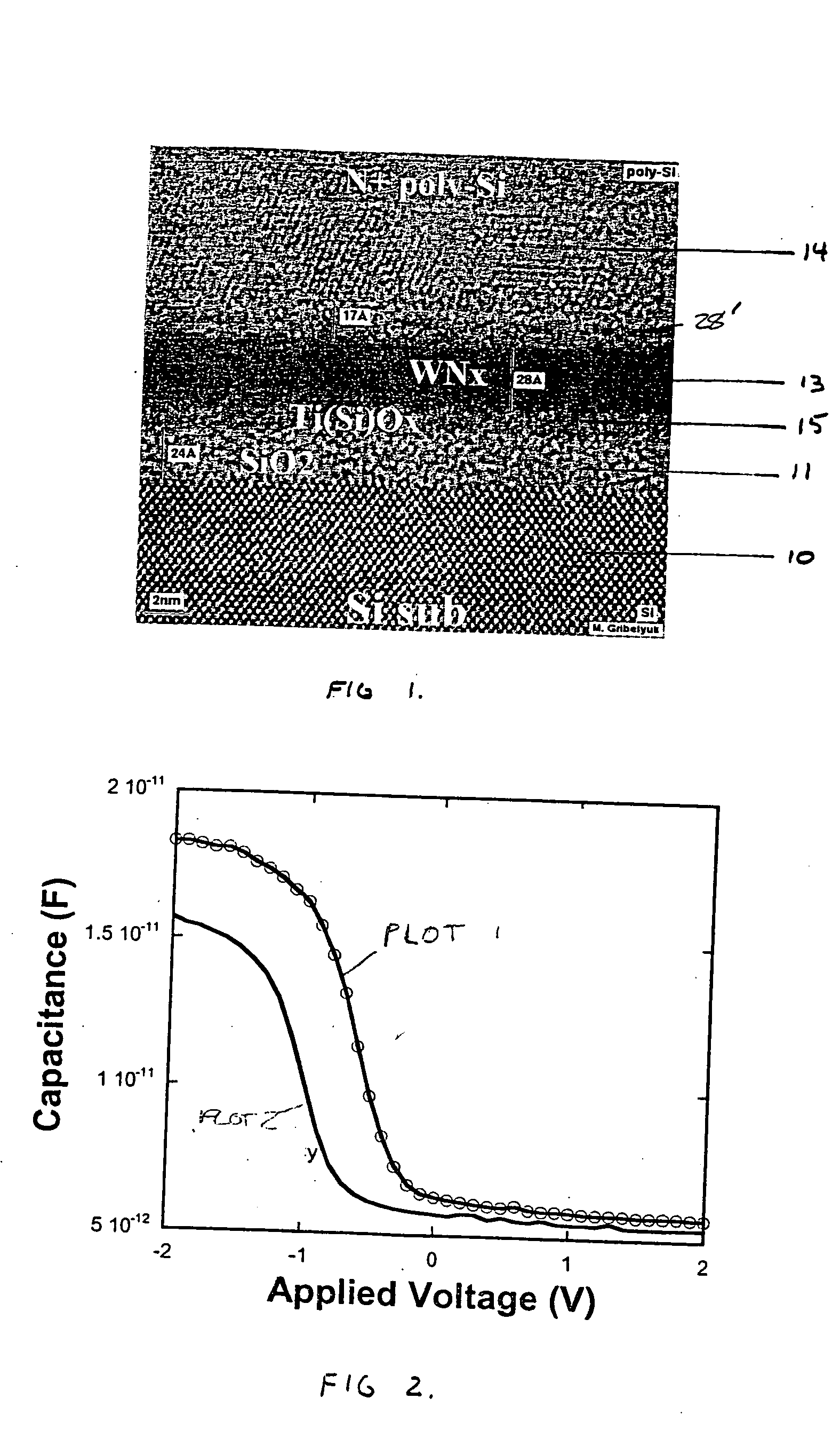
[0039] The present invention provides high-k gate dielectrics comprising uniform continuous ultra-thin high-k metal oxide layers, and a method of forming the same. The present invention advantageously provides a continuous ultra-thin high-k metal oxide layer by depositing a highly reactive layer of metal atoms atop a dielectric surface comprising at least silicon and oxygen atoms and forming an oxygen diffusion barrier atop the layer of metal atoms, in which the highly reactive layer of metal atoms and the oxygen diffusion barrier are formed in a non-oxidizing atmosphere. Following the deposition of a gate conductor atop the oxygen diffusion barrier, the highly reactive metal atom layer completely reacts with the dielectric surface to provide a continuous ultra-thin high-k metal oxide layer during subsequent annealing. Specifically, the metal atoms of the layer of metal atoms bonds with the oxygen atoms of the dielectric layer, thus converting the upper surface of the dielectric lay...


PUM


Abstract

The present invention provides a method for depositing a dielectric stack comprising forming a dielectric layer atop a substrate, the dielectric layer comprising at least oxygen and silicon atoms; forming a layer of metal atoms atop the dielectric layer within a non-oxidizing atmosphere, wherein the layer of metal atoms has a thickness of less than about 15 Å; forming an oxygen diffusion barrier atop the layer of metal atoms, wherein the non-oxidizing atmosphere is maintained; forming a gate conductor atop the oxygen diffusion barrier; and annealing the layer of metal atoms and the dielectric layer, wherein the layer of metal atoms reacts with the dielectric layer to provide a continuous metal oxide layer having a dielectric constant ranging from about 25 to about 30 and a thickness less than about 15 Å.

Description

RELATED APPLICATION [0001] This application is related to co-pending and co-assigned U.S. application Ser. No. ______ (FIS920040164US1) entitled TEMPERATURE STABLE METAL NITRIDE GATE ELECTRODE, filed on the same date. The entire content of this related application is incorporated by reference.FIELD OF THE INVENTION [0002] The present invention relates to a method for forming gate dielectrics, and more particularly, to a method for depositing a continuous high-k dielectric having a thickness on the order of about 15 Å or less. The term “high-k” denotes a dielectric material that has a dielectric constant of about 20 or greater. The term “continuous” denotes a continuously present layer of dielectric material, free of island growth. BACKGROUND OF THE INVENTION [0003] With decreasing gate lengths in metal oxide semiconductor field effect transistors (MOSFET), thin dielectrics are necessary to increase drive current and improve short channel behavior. [0004] Conventional methods for for...

Claims


Application Information

Patent Timeline
IPC IPC(8): H01L21/28H01L21/336H01L21/44H01L29/49H01L29/51
CPCH01L21/28088H01L21/28176H01L21/28185H01L29/66545H01L29/4966H01L29/513H01L29/517H01L21/28229
Inventor PARK, DAE-GYUGLUSCHENKOV, OLEG G.GRIBELYUK, MICHAEL A.WONG, KWONG HON
Owner GLOBALFOUNDRIES INC
Why Eureka
Try Eureka