Medical implant having closed loop transcutaneous energy transfer (TET) power transfer regulation circuitry

a technology of power transfer regulation circuit and implant device, which is applied in the field of medical implantable devices, can solve the problems of inability device performance erratically or fail to function at all, and inability to meet the needs of patients, etc., and achieve the effect of less susceptible to damage or inoperability

Inactive Publication Date: 2005-12-29
ETHICON ENDO SURGERY INC
View PDF25 Cites 396 Cited by
  • Summary
  • Abstract
  • Description
  • Claims
  • Application Information

AI Technical Summary

Benefits of technology

[0016] The invention overcomes the above-noted and other deficiencies of the prior art by providing an implantable medical device having receiving circuitry for transcutaneous energy transfer (TET) from primary circuitry external to a patient. In particular, the receiving circuitry performs voltage regulation sufficient to support active components, such as integrated circuitry, without resorting to batteries. Moreover, insofar as the receiving circuitry adjusts power transfer autonomously with regard to the primary circuitry, the implantable medical device is less susceptible to damage or inoperability due to variations in a power channel formed with the primary circuitry.

Problems solved by technology

Variations in the spacing can cause changes in the AC magnetic field strength reaching the secondary coil, in turn causing power fluctuations and surges in the implant device.
Variations in the supplied power, such as sudden changes in voltage or current levels, may cause the device to perform erratically or fail to function at all.
Accordingly, one issue associated with conventional TET systems is that the physical displacement of either the primary or secondary coils from an optimum coupling position may cause an unacceptable effect on the output power supplied to the implanted device.
These load variations create different demands on the TET system, and lead to inconsistencies in the output power required to drive the load.
While apparently an effective approach to power regulation in a TET system, it is believed in some applications that this approach has drawbacks.
For high impedance secondary coils, shorting the secondary circuit in this manner may create excessive heating, especially should the primary circuit continue to provide excessive power to the secondary circuit.
In particular, the power consumed to pump fluid is significant, as compared to what would be required for only powering control circuitry, for example.
Moreover, powering the active pumping components need only occur intermittently.

Method used


Image

  • Medical implant having closed loop transcutaneous energy transfer (TET) power transfer regulation circuitry
  • Medical implant having closed loop transcutaneous energy transfer (TET) power transfer regulation circuitry
  • Medical implant having closed loop transcutaneous energy transfer (TET) power transfer regulation circuitry

Examples


first embodiment

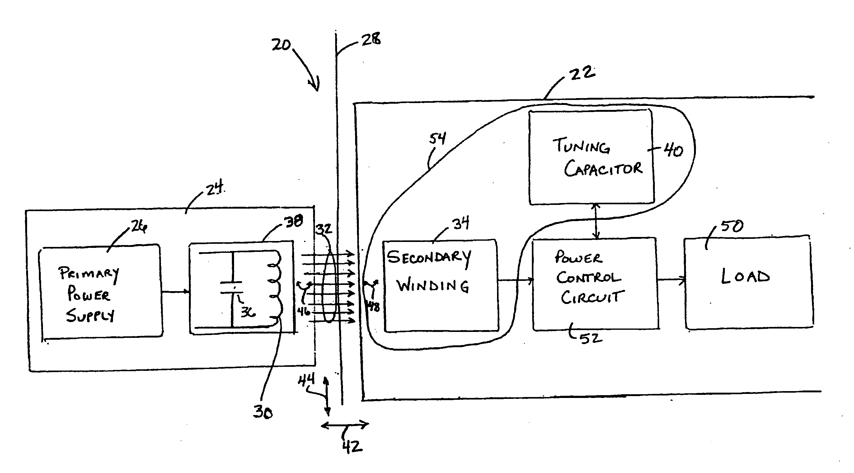
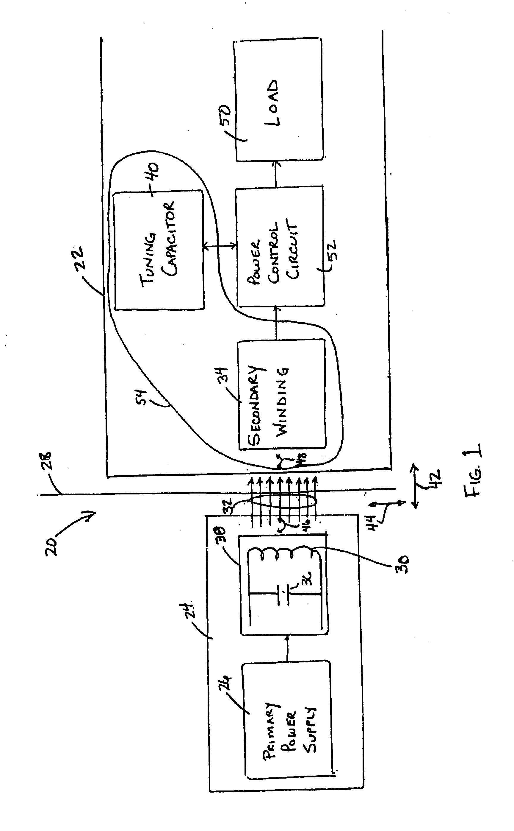
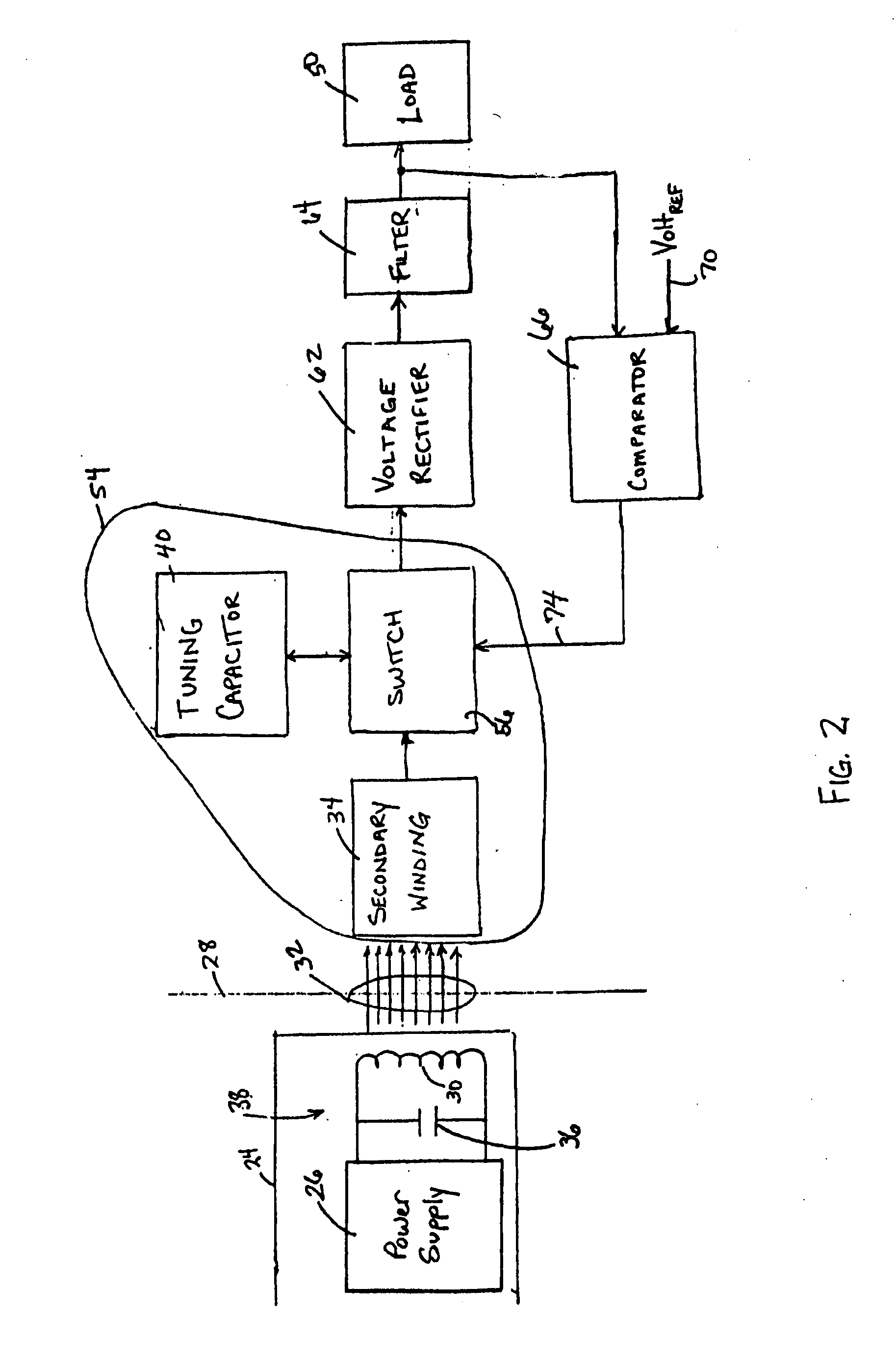
[0040] In a first embodiment shown in FIG. 2, power control circuit 52 comprises a switch 56 that internally modulates the power signal induced in secondary coil 34 to control the power output to load 50. Switch 56 modulates the power signal by selectively detuning secondary resonant circuit 54 when the voltage output to load 50 exceeds a predetermined threshold level. A suitable switch 56 may include a solid state switch such as a triac or silicon controlled rectifier (SCR). The secondary resonant circuit 54 is detuned by placing switch 56 in the resonant circuit, and selectively closing the switch 56 to short-circuit either tuning capacitor 40 or secondary coil 34. Short-circuiting either capacitor 40 or coil 34 causes secondary resonant circuit 54 to lose resonance, thereby preventing energy transfer through coil 34 to load 50. When the load voltage drops below the voltage threshold, switch 56 is opened to again transfer power to load 50. By repeatedly detuning and then retuning ...

second embodiment

[0051]FIG. 7 provides a detailed schematic diagram illustrating the invention. The schematic in FIG. 7 is similar to the schematic in FIG. 4 except for the relocation of switch 56. As shown in FIG. 7, in this exemplary embodiment switch 56 comprises a solid-state relay between full-wave rectifier 62 and filter capacitors 64. An output signal from comparator 66 turns the relay on and off, based upon the output power to load 50. While switch 56 is depicted as a solid-state relay, numerous other types of switching devices could also be used to accomplish the present invention.

[0052]FIG. 8 illustrates an alternative embodiment for the power control circuit 52 of the present invention. In the alternative embodiment, comparator 66 in the closed loop power control system is replaced with a Proportional, Integral, Derivative (PID) controller 90. PID controller 90 activates switch 56 to pulse width modulate the power signal. PID controller 90 modulates the power signal by first calculating t...


PUM


Abstract

An implantable medical device, such as a bi-directional infuser device for hydraulically controlling an artificial sphincter (e.g., adjustable gastric band) benefits from being remotely powered by transcutaneous energy transfer (TET), obviating the need for batteries. In order for active components in the medical device to operate, a sinusoidal power signal received by a secondary coil is rectified and filtered. An amount of power transferred is modulated. In one version, a voltage comparison is made of a resulting power supply voltage as referenced to a threshold to control pulse width modulation (PWM) of the received sinusoidal power signal, achieving voltage regulation. Versions incorporate detuning or uncoupling of the secondary coil to achieve PWM control without causing excessive heating of the medical device.

Description

CROSS REFERENCE TO RELATED APPLICATIONS [0001] The present application is related to four co-pending and commonly-owned applications filed on even date herewith, the disclosure of each being hereby incorporated by reference in their entirety, entitled respectively: [0002]“TRANSCUTANEOUS ENERGY TRANSFER PRIMARY COIL WITH A HIGH ASPECT FERRITE CORE” to James Giordano, Daniel F. Dlugos, Jr. & William L. Hassler, Jr., Ser. No. ______; [0003]“MAGNETIC RESONANCE IMAGING (MRI) COMPATIBLE REMOTELY ADJUSTABLE GASTRIC BAND” to William L. Hassler, Jr. et al., Ser. No. ______; [0004]“SPATIALLY DECOUPLED TWIN SECONDARY COILS FOR OPTIMIZING TRANSCUTANEOUS ENERGY TRANSFER (TET) POWER TRANSFER CHARACTERISTICS” to Resha H. Desai, William L. Hassler, Jr., Ser. No. ______; [0005]“LOW FREQUENCY TRANSCUTANEOUS TELEMETRY TO IMPLANTED MEDICAL DEVICE” to William L. Hassler, Jr., Ser. No. ______; and [0006]“LOW FREQUENCY TRANSCUTANEOUS ENERGY TRANSFER TO IMPLANTED MEDICAL DEVICE” to William L. Hassler, Jr.,...

Claims


Application Information

Patent Timeline
Patent Type & Authority Applications(United States)
IPC IPC(8): A61F2/00A61F2/02A61F2/48A61N1/08A61N1/378
CPCA61F2/0036A61N1/3787A61F2250/0001A61N1/37223A61F5/0059
Inventor HASSLER, WILLIAM L. JR.BLOOM, GORDON EDWARD
Owner ETHICON ENDO SURGERY INC
Why Eureka
Try Eureka