Light-emitting diode

Active Publication Date: 2006-01-05
CITIZEN ELECTRONICS CO LTD
View PDF7 Cites 60 Cited by
  • Summary
  • Abstract
  • Description
  • Claims
  • Application Information

AI Technical Summary

Benefits of technology

[0011] The object of the present invention is to provide a high-luminance type LED which minimizes power loss in the form of heat and enables

Problems solved by technology

These colored light illuminating LEDs and high output type LEDs consume a large amount of electricity and therefore heat dissipation becomes an important issue.
However, increasing the driving current results in a proportionally larger power loss in the LED element.
Most of this power loss is transformed into thermal energy, which in turn increases the temperature of the LED element itself.
Since the LED element has the characteristic that its light emission efficiency (current-light conversion efficiency) increases as the temperature lowers, the problem arises that the brightness of light to be produced decreases as the temperature inside the LED element increases.
Another problem is that heat-induced discoloration of the light-transmitting resin material sealing the LED element degrades its transparency.
These problems have made it difficult to realize the commercialization of LEDs that meet both the requirements of high output and high reliability such as longevity.
For example, when a metal core substrate with an excellent heat conductivity is used for the printed ci

Method used


Image

  • Light-emitting diode
  • Light-emitting diode
  • Light-emitting diode

Examples


first embodiment

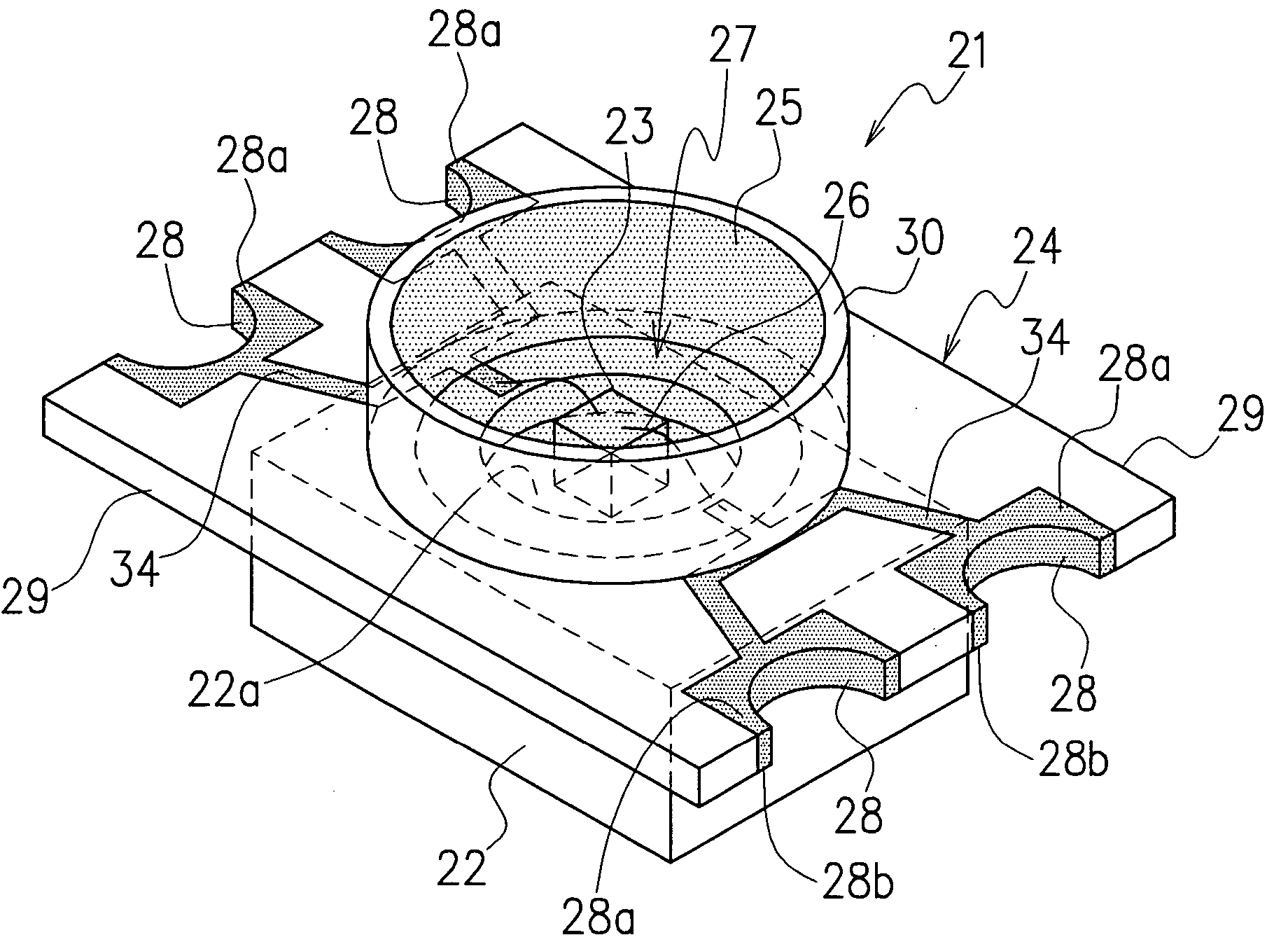
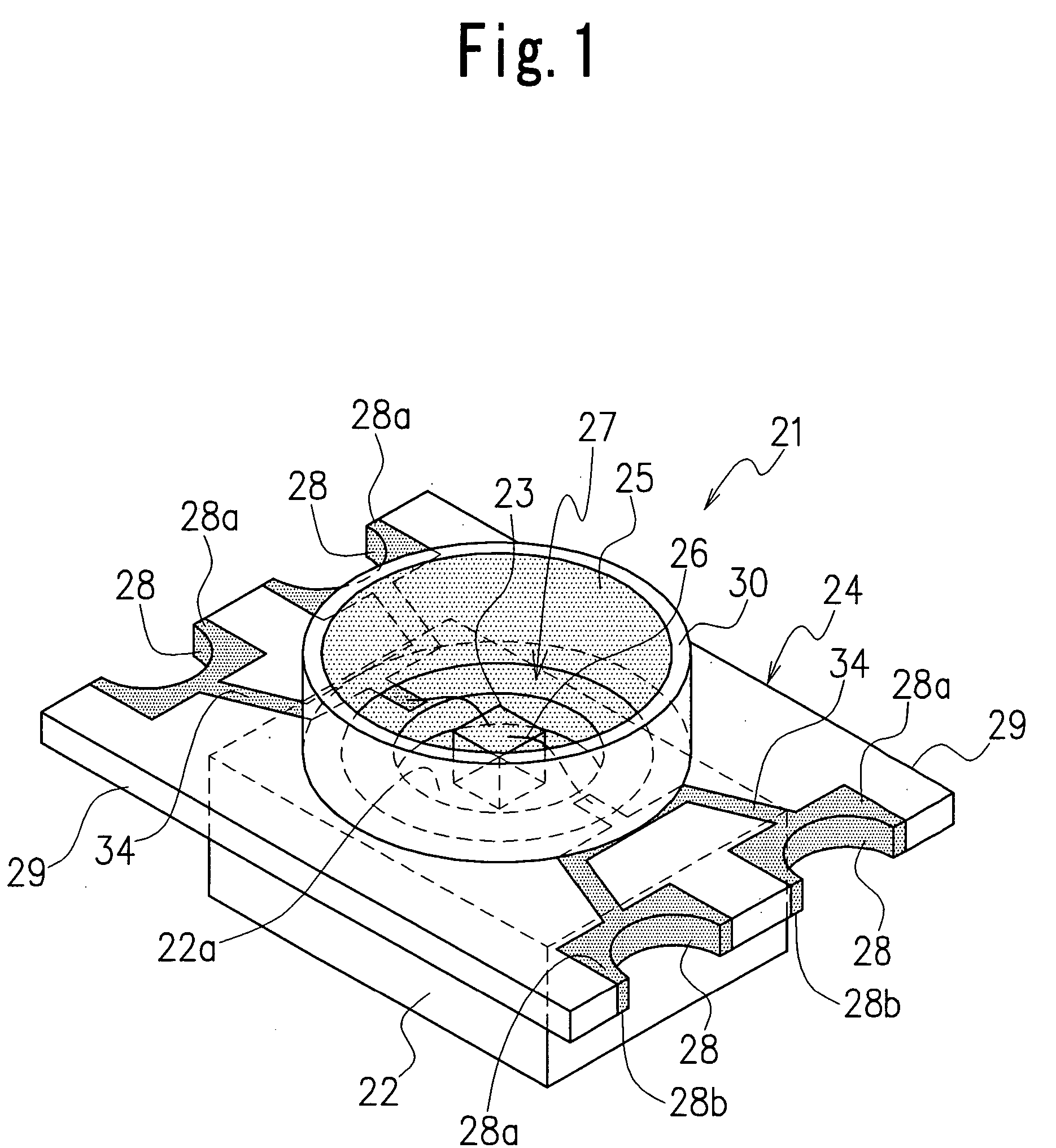
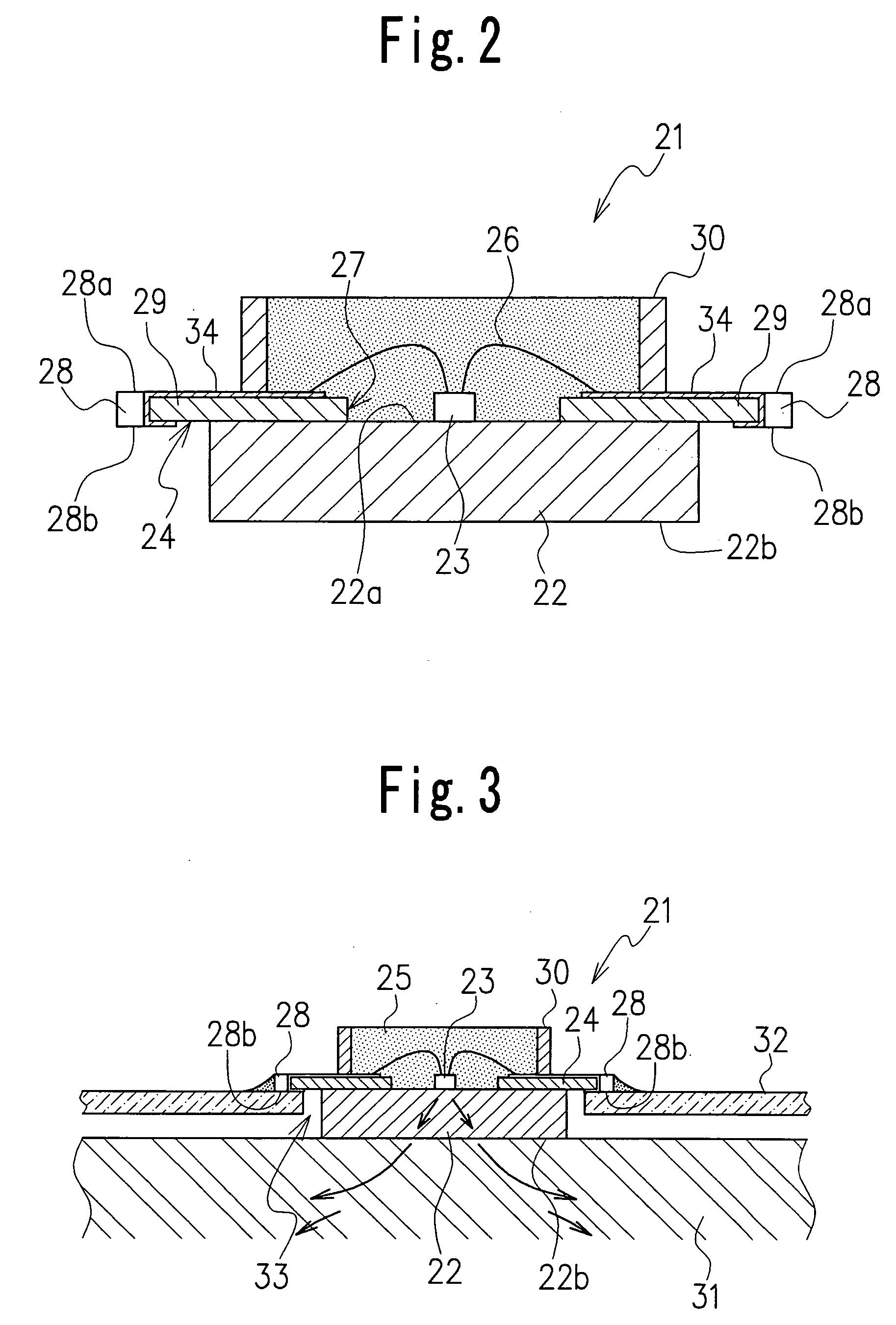
[0026]FIG. 1 and FIG. 2 show an LED as the invention. This LED 21 comprises a base 22 having high thermal conductivity; at least one LED element 23 fixed at an almost central part of the base 22; an LED printed circuit board 24 mounted on the upper surface of the base 22 to surround the LED element 23; and a light-transmitting resin material 25 sealing the LED element 23.

[0027] The base 22 is formed from a material with high thermal conductivity, such as metal materials including copper, copper alloy, aluminum and aluminum alloy, to enhance the heat dissipating effect. The base 22 provides a surface 22a on which the LED element 23 is to be die-bonded. The underside of the base 22 forms a heat dissipating surface 22b that releases heat by making contact with, for instance, a frame of another electronic device wherein the LED is used. For an increased heat dissipating effect, it is preferable that the heat dissipating surface 22b be widened. It is therefore effective to form the base ...

second embodiment

[0038]FIG. 5 shows another LED as this invention. In the LED 41, an LED element 43 has a pair of element electrodes formed on each of the upper and lower surfaces of an LED element 43, respectively. A sub-mount substrate 44 is placed on the mounting surface 22a of the base 22 and the element electrode on the underside of the LED element 43 is die-bonded to the upper surface of this sub-mount substrate 44. A bonding wire 26a is provided to connect the element electrode on the upper surface of the LED element 43 to the electrode patterns formed on the printed circuit board 24. The sub-mount substrate 44 is formed from, for instance, an aluminum-based ceramics or silicon substrate for an enhanced heat dissipation effect. Two patterns are formed on the surface of the sub-mount substrate 44. One is a die bond pattern, on which the element electrode on the underside of the LED element 43 is surface-mounted, and the other is a lead-out pattern extended from the die bond pattern, which is c...

fourth embodiment

[0041]FIG. 7 shows yet another LED as this invention. The LED 61 has LED elements 63a, 63b, 63c, which emit three primary colors of light—red, blue and green—respectively, mounted on a mounting surface 62a of a base 62. Through-holes constructed of anode electrodes (A1-A3) and cathode electrodes (K1-K3), that are assigned to these LED elements 63a, 63b, 63c, are formed at the two facing ends such as the left and right ends of the protruding portion 69 of a printed circuit board 64. The printed circuit board 64 has a circular hole 67 which exposes the LED elements 63a, 63b, 63c, and a seal frame 70 is provided to surround the LED elements 63a, 63b, 63c. This LED 61 can be made to emit a variety of colors of light by adjusting the voltage applied to the anode electrodes (A1-A3) and the cathode electrodes (K1-K3). The large amount of heat produced by the plurality of LED elements can be effectively dissipated through the base 62.


PUM


Abstract

The LED comprises: a base having high thermal conductivity and having a mounting surface for die bonding; a printed circuit board mounted on the base and having a hole to expose a part of the mounting surface of the base and having a protruding portion projecting horizontally outward on the outer periphery of the base; an LED element mounted on the mounting surface of the base exposed in the hole of the printed circuit board; and a resin material sealing the LED element from above; wherein through-holes electrically connected to the LED element are formed at the outer periphery of the protruding portion and an external connection electrode is provided to the upper and lower surfaces of the through-holes. This LED enhances the heat dissipating effect to enable generation of high-luminance light and can also be mounted on either the upper or lower surface of a motherboard.

Description

CROSS-REFERENCE TO THE RELATED APPLICATION [0001] The application claims the priority benefit of Japanese Patent Application No. 2004-182403 filed on Jun. 21, 2004, the entire descriptions of which are incorporated herein by reference. BACKGROUND OF THE INVENTION [0002] 1. Field of the Invention [0003] The present invention relates to a high-luminance type light-emitting diode (LED) with a heat dissipation function. [0004] 2. Related Art Statement [0005] Light-emitting diodes (LEDs) that have been used as a backlight source for the liquid crystal panels of cell phones and other devices are characteristically small in size with a long life as a light source. In recent years, various types of LEDs have been commercialized, including one that emits colored light and one with high output that illuminates a relatively wide area at high brightness. These colored light illuminating LEDs and high output type LEDs consume a large amount of electricity and therefore heat dissipation becomes a...

Claims


Application Information

Patent Timeline
IPC IPC(8): H01J1/62H01L33/60H01L33/64H05K1/02H05K1/18H05K3/34
CPCH01L33/486H01L33/64H01L2924/10253H01L2224/48091H05K2201/10106H05K1/0204H05K1/021H05K1/182H05K3/0061H05K3/3442H05K2201/09181H01L2924/00014H01L2924/00
Inventor IMAI, SADATOKIKUCHI, SATORU
Owner CITIZEN ELECTRONICS CO LTD
Why Eureka
Try Eureka