
Method of making scratch resistant coated glass article including layer(s) resistant to fluoride-based etchant(s)

a fluoride-based etchant and coating technology, applied in the direction of transportation and packaging, nuclear engineering, railway signalling, etc., can solve the problems of small thicknesses giving rise to micro-particulates on the substrate, and vandals are increasingly turning to glass

Inactive Publication Date: 2006-01-05
HER MAJESTY THE QUEEN AS REPRESENTED BY THE MINIST OF NAT DEFENCE OF HER MAJESTYS CANADIAN GOVERNMENT +1
View PDF36 Cites 61 Cited by
  • Summary
  • Abstract
  • Description
  • Claims
  • Application Information

AI Technical Summary

Benefits of technology

This patent describes a method for making a scratch resistant coated article that is also resistant to attacks by fluoride-based etchants for at least a period of time. The method involves depositing an anti-etch layer on the glass substrate using an ion beam, which results in a layer that is more resistant to HF acid exposure than a purely sputtered counterpart. An underlayer may also be provided under the anti-etch layer, which may comprise diamond-like carbon or some other dielectric. The anti-etch layer may comprise one or more of silicon carbide nitride, hydrogenated silicon carbide nitride, zirconium oxycarbide, zirconium carbide, hydrogenated zirconium oxycarbide, hydrogenated zirconium carbide, tin oxycarbide nitride, indium oxide, indium molybdenum oxide, cerium oxide, indium tin oxide, and / or magnesium oxide. The coated article may be used in applications where resistance to fluoride-based etchants is required.

Problems solved by technology

Unfortunately, vandals have increasingly been turning to glass etchants as a tool of choice for graffiti.
Unfortunately, these coatings are susceptible to damage and are not very scratch resistant thereby rendering their use in environments such as subway cars, buses and vehicles undesirable.
While carbon is resistant to fluoride ion (and F2−) attack, these layers when formed via ion beam deposition techniques at very small thicknesses give rise to micro-particulates on the substrate.

Method used


Image

  • Method of making scratch resistant coated glass article including layer(s) resistant to fluoride-based etchant(s)
  • Method of making scratch resistant coated glass article including layer(s) resistant to fluoride-based etchant(s)
  • Method of making scratch resistant coated glass article including layer(s) resistant to fluoride-based etchant(s)

Examples


examples

[0046] The following examples are provided for purposes of example only and are not intended to be limiting unless expressly claimed.

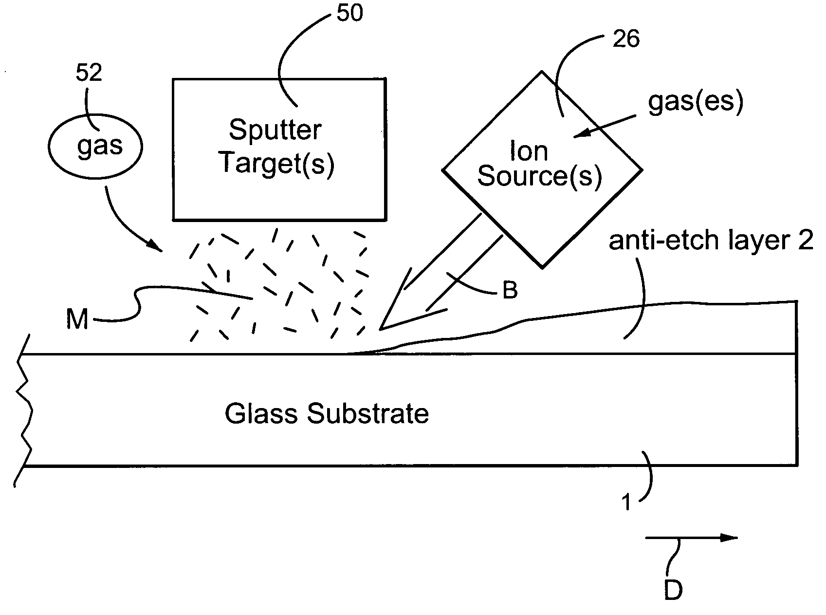
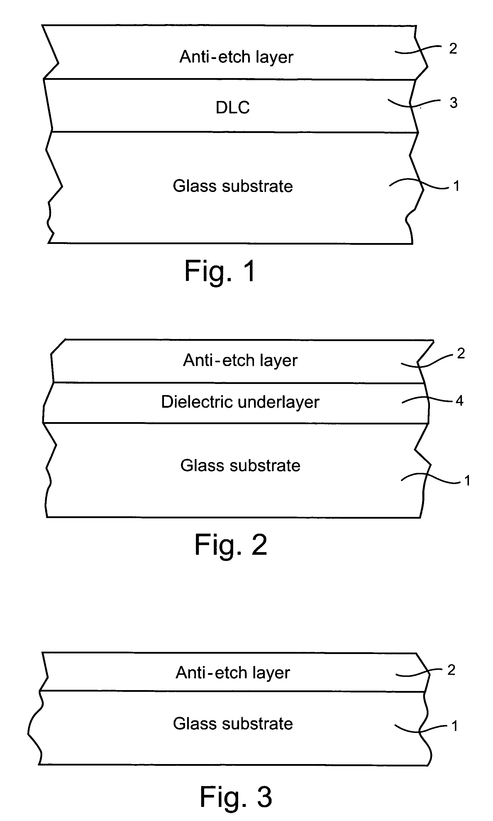
[0047] In a first example, a hydrogenated silicon carbide nitride (SiCxNy:H) anti-etch layer 2 was deposited using IBAD over a DLC based layer 3 on a glass substrate 1 (e.g., see FIG. 1). The DLC layer 3 was about 100 angstroms thick, and the anti-etch layer 2 was about 1530-1565 angstroms thick. The glass substrate was 2.3 mm thick. The IBAD conditions used in depositing the anti-etch layer 2 were as follows: [0048] a) Planar SiC sputtering target [0049] b) 0.38 m linear ion source positioned 30 degrees from the horizontal [0050] c) Ar gas flow by the sputtering target=150 sccm [0051] d) Acetylene gas flow through the ion source=20 sccm [0052] e) NH3 gas flow through the ion source=5 sccm [0053] f) Pressure=2.69 mT [0054] g) Magnetron sputtering power of 2.3 kW from 665V and 3.4A [0055] h) 3 kV voltage for ion source which produced 0.26 A

[0056] Opti...


PUM

PropertyMeasurementUnit
pHaaaaaaaaaa
transparentaaaaaaaaaa

Abstract

A method is provided for making a coated article including an anti-etch layer(s) that is resistant to attacks by at least some fluoride-based etchant(s) for at least a period of time. In certain example embodiments, an anti-etch layer(s) is provided on a glass substrate in order to protect the glass substrate from attacks by fluoride-based etchant(s). In certain example embodiments, the anti-etch layer(s) is formed using at least one ion beam (possibly in combination with at least one sputtering target). In certain embodiments, a diamond-like carbon (DLC) inclusive layer(s) may be provided over and / or under the anti-etch layer.

Description

[0001] This application claims priority on U.S. Provisional Patent Application Nos. 60 / 529,624, filed Dec. 16, 2003, and 60 / 529,103, filed Dec. 15, 2003, and furthermore this application is a continuation-in-part (CIP) of U.S. patent application Ser. No. 10 / 989,721, filed Nov. 17, 2004, and of Ser. No. 10 / 899,305, filed Jul. 27, 2004, the entire disclosures of which are all hereby incorporated herein by reference. [0002] This application relates to a coated article including a coating supported by a glass substrate, and a method of making the same. The coating includes an anti-etch layer that is resistant to fluoride-based etchant(s), and may also include other layer(s) such as a scratch-resistant layer comprising diamond-like carbon (DLC). Coated articles according to different embodiments of this invention may be used as windows or in any other suitable application.BACKGROUND OF THE INVENTION [0003] Unfortunately, vandals have increasingly been turning to glass etchants as a tool ...

Claims


Application Information

Patent Timeline
Patent Type & Authority Applications(United States)
IPC IPC(8): B32B17/06C23C14/32B05D3/00B32B9/00C08J7/18C23C14/00C23C16/00C23C16/26G21H5/00H01L21/4763
CPCC03C17/225C03C17/245C03C17/3417C03C17/3435C23C14/0664C03C2217/281C03C2217/282C23C14/0052C03C17/3441
Inventor VEERASAMY, VIJAYEN S.
Owner HER MAJESTY THE QUEEN AS REPRESENTED BY THE MINIST OF NAT DEFENCE OF HER MAJESTYS CANADIAN GOVERNMENT
Learn More