
Multiple-label fluorescence imaging using excitation-emisssion matrices

Inactive Publication Date: 2006-01-12
CORCORAN TIMOTHY C
View PDF28 Cites 31 Cited by
  • Summary
  • Abstract
  • Description
  • Claims
  • Application Information

AI Technical Summary

Benefits of technology

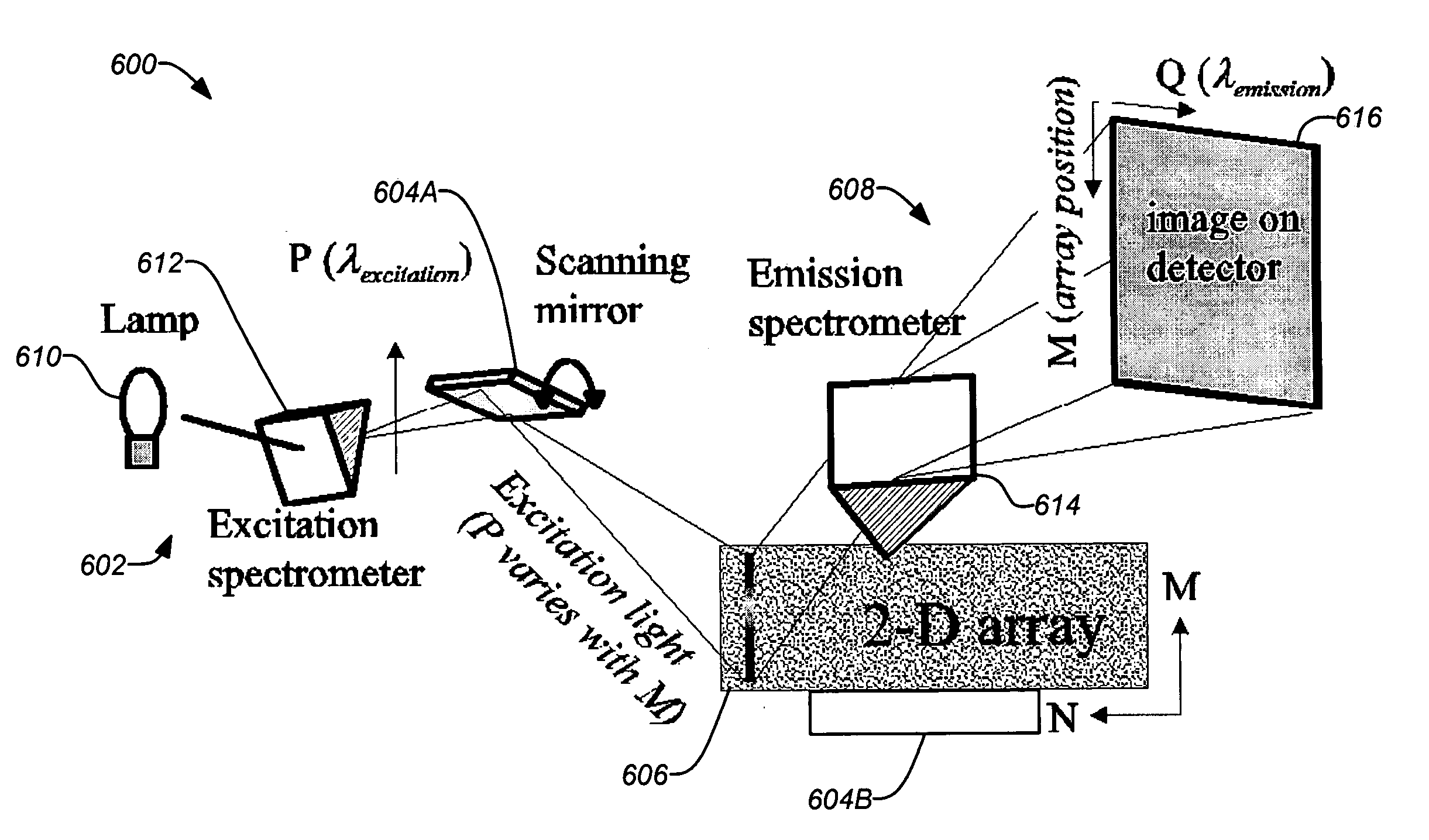
[0028] Various embodiments of the invention address the process of imaging fluorescently labeled heterogeneous, two-dimensional samples, such as microarrays, labs-on-a-chip and gels used in genetic, protein and other separation and / or purification processes, as well as other two-dimensional fluorescent samples. Embodiments of the invention allow a considerably larger number of fluorescent labels to be used simultaneously than previously. This may be accomplished by employing a spectroscopic technique using an EEM which allows discrimination of species having similar fluorescent spectra. In addition, embodiments of the invention may employ a novel excitation-light scanning technique to maximize the throughput of excitation light, increasing the sensitivity and reading speed.
[0032] In further embodiment the stored excitation-emission matrix may be analyzed with a data processor. Operating on the data of the excitation-emission matrix, the data processor can identify sample emission due to energy transfer between at least two emitting species. In addition, the data processor can also identify a signature in the data of the excitation-emission matrix of a donor species and an acceptor species having the properties of the donor species along an excitation wavelength axis and the properties of the acceptor species along an emission wavelength axis. Furthermore, the data processor can correct error in quantification of amount of the at least two emitting species due to the energy transfer between the at least two emitting species from the data of the excitation-emission matrix.

Problems solved by technology

In part, this fundamental limitation arises from the use of optical filters to separate the fluorescence of the different labels employed.
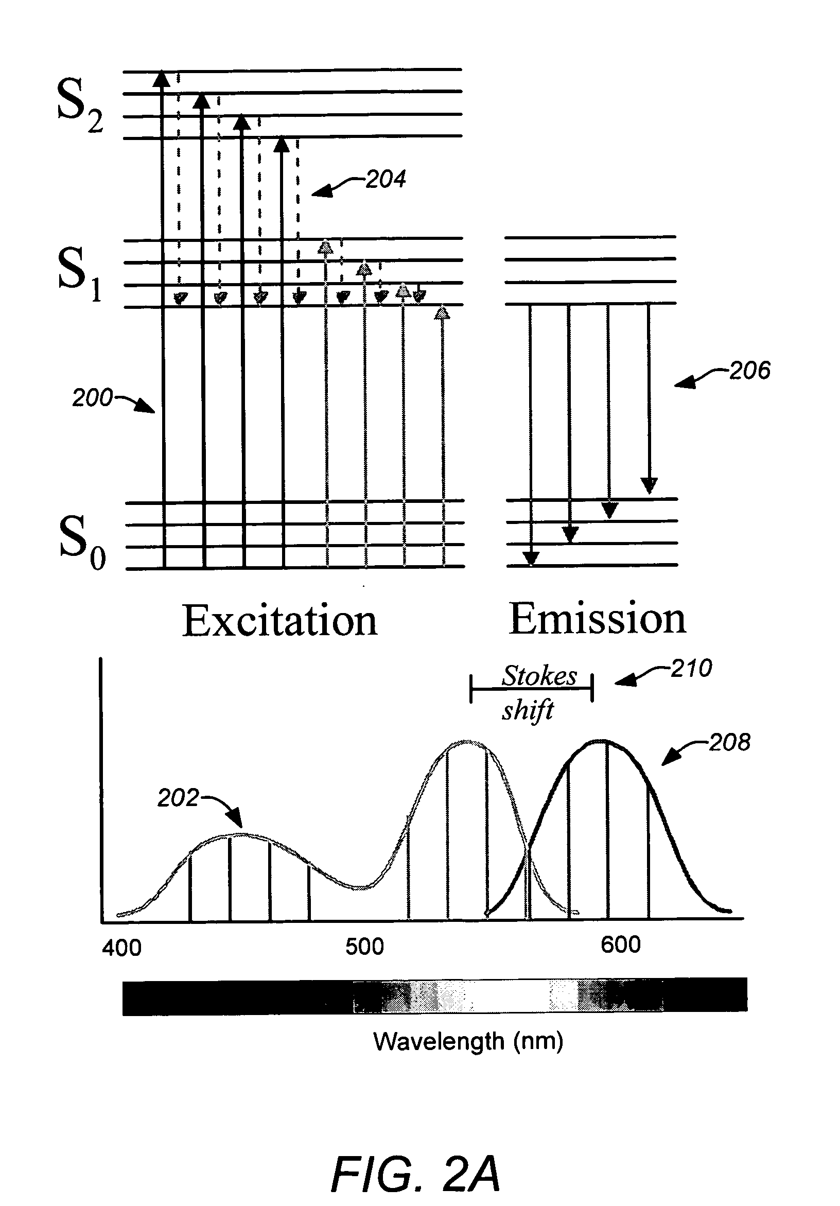
Moreover, if a large number of different fluorescent labels were employed, performance would be very limited because all the labels would not have well separated fluorescent spectra; the spectra begin to overlap, and optical filters would no longer clearly resolve different label species under this condition.
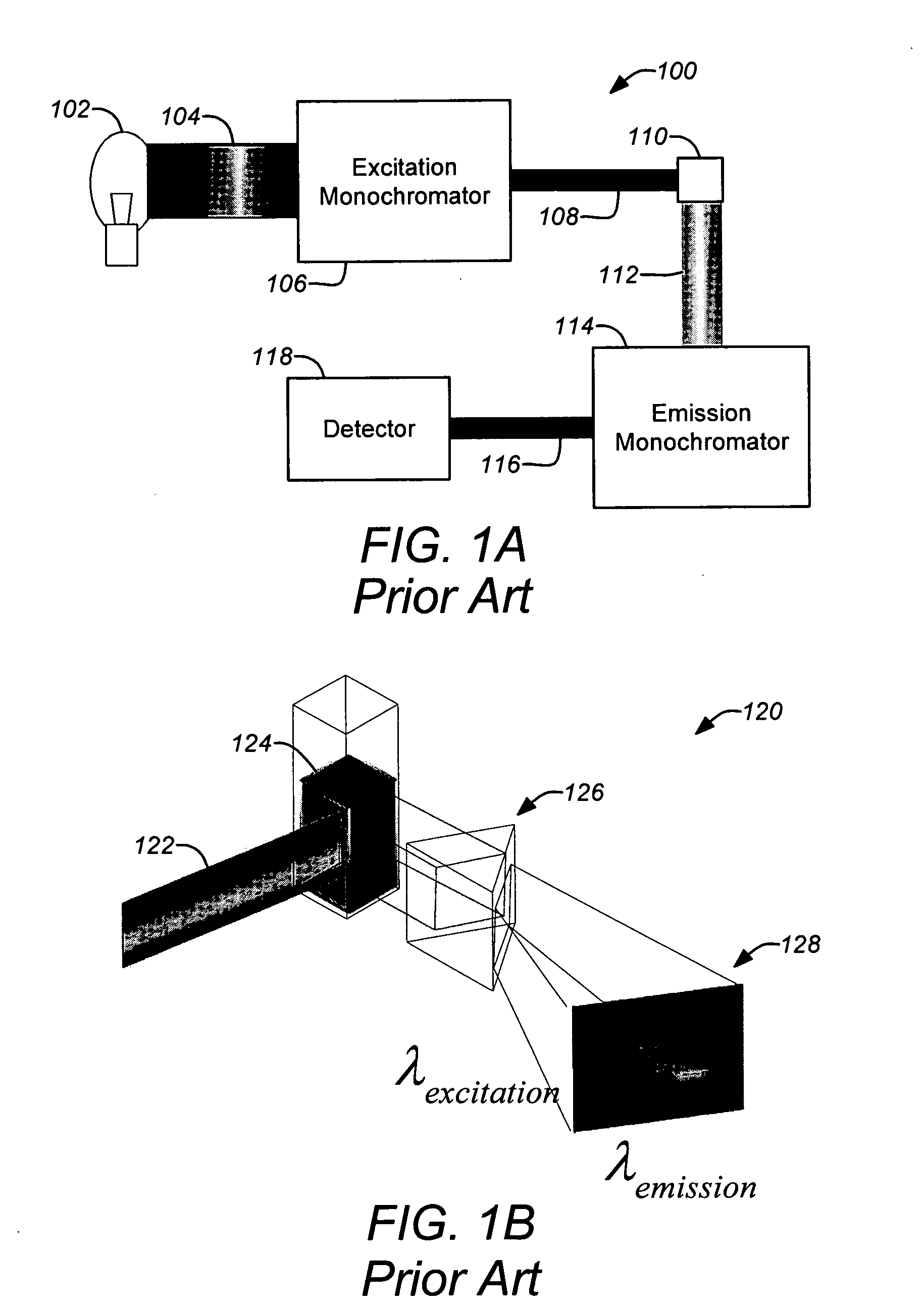
Other spectroscopic techniques with better wavelength resolution generally have greater losses and lower throughput due to the optical devices employed (such as spectrometer slits, mirrors and gratings).
This can significantly limit sensitivity and hence readout speed.
However, the authors restricted their work to simple, homogenous samples and no spatial resolution was incorporated.
Due to the long path of the light beam, positioning inaccuracies of the tilting mirrors result in major position inaccuracies of the scanning ray bundle on the surface of the sample.
If spot detectors without spatial resolution are used, the detector must be read out and re-initialized after the illumination of each scanning spot on the sample; this results in a waiting time before the scanning beam can be moved to the next scanning spot and, consequently, in a reduction of the read-out velocity.
In view of the foregoing, the prior art does not demonstrate a method for combining the advantages of the EEM in quantitative analysis of fluorescent species which have substantially overlapped spectra, with imaging capability necessary for spatially characterizing a sample consisting of a two-dimensional, heterogeneous array.

Method used


Image

  • Multiple-label fluorescence imaging using excitation-emisssion matrices
  • Multiple-label fluorescence imaging using excitation-emisssion matrices
  • Multiple-label fluorescence imaging using excitation-emisssion matrices

Examples


Embodiment Construction

[0050] In the following description of the preferred embodiment, reference is made to the accompanying drawings which form a part hereof, and in which is shown by way of illustration a specific embodiment in which the invention may be practiced. It is to be understood that other embodiments may be utilized and structural changes may be made without departing from the scope of the present invention.

1. Overview

[0051] The present invention discloses methods and devices which apply an excitation-emission matrix (EEM) to a heterogeneous, two-dimensional sample, allowing a considerably larger number of fluorescent labels to be used simultaneously. This may be accomplished by employing a spectroscopic method of excitation-emission matrices which allows discrimination of species with similar fluorescent spectra. Embodiments of the invention may employ a novel excitation-light scanning technique which maximizes the throughput of excitation light, increasing the sensitivity and hence the r...


PUM


Abstract

Methods and devices are disclosed which apply an excitation-emission matrix (EEM) to a heterogeneous, two-dimensional sample, allowing a considerably larger number of emitting, e.g. fluorescent, labels to be used simultaneously. This may be accomplished by employing a spectroscopic method of excitation-emission matrices which allows discrimination of species with similar emission spectra, and also allows positive identification of energy transfer between emitting species. The methods and devices may employ a novel excitation-light scanning technique which allows imaging of the emission from the heterogeneous sample both in two spatial dimensions (length and width) and in two spectral dimensions (excitation and emission wavelength). This light scanning technique maximizes the throughput of excitation light, increasing the sensitivity and hence the reading speed of the instrument.

Description

[0001] This application claims the benefit under 35 U.S.C. §119(e) of the following co-pending U.S. provisional patent application, which is incorporated by reference herein: [0002] U.S. Provisional Application Ser. No. 60 / 586,435, filed Jul. 7, 2004, by Timothy C. Corcoran, entitled “MULTIPLE-LABEL FLUORESCENCE IMAGER USING EXCITATION-EMISSION MATRICES (EEM IMAGER)-DEVICE AND METHOD”.BACKGROUND OF THE INVENTION [0003] 1. Field of the Invention [0004] The present invention relates to systems and methods for fluorescently imaging labeled two-dimensional samples. Particularly, this invention relates to such systems and methods applied to DNA microarrays and gels used in protein and other biological or chemical separation and / or purification processes, as well as other two-dimensional fluorescent or luminescent samples. [0005] 2. Description of the Related Art [0006] Current fluorescent imaging systems, such as those most commonly employed in biotechnology, read only a limited number f...

Claims


Application Information

Patent Timeline
IPC IPC(8): G01J3/30
CPCG01J3/02G01J3/021G01J3/14G01J3/4406G01N21/6428G01N21/6452G01N2201/1042G01N21/6486G01N2021/6417G01N2021/6423G01N2021/6441G01N2021/6463G01N2201/10G01N21/6456
Inventor CORCORAN, TIMOTHY C.
Owner CORCORAN TIMOTHY C
Learn More