Fuel cell with in-cell humidification

a fuel cell and in-cell technology, applied in the direction of fuel cells, fuel cell auxilaries, electrical equipment, etc., can solve the problems of reduced output current, reduced power supply, and inability to support the electrochemical reaction occurring in the fuel cell at a sufficient state, so as to improve the reliability of the fuel cell, simplify the fuel cell system design and manufacturing, and increase the compactness

Inactive Publication Date: 2006-01-12
HYTEON
View PDF77 Cites 28 Cited by
  • Summary
  • Abstract
  • Description
  • Claims
  • Application Information

AI Technical Summary

Benefits of technology

[0013] The invention relates to a fuel cell plate integrating an active flow field zone for carrying out electrochemical reaction and at least one humidification zone for humidifying reactant streams. The area of the humidification field is proportionally designed to the fuel cell active flow field so that an adequate humidity and temperature can be achieved for fuel cell systems that can have different capacities, under which resizing the humidifier would be otherw

Problems solved by technology

If the membrane dries out, its resistance to the flow of protons increases, the electrochemical reaction occurring in the fuel cell can no longer be supported at a sufficient state, and consequently the output current decreases or, in the worst case, stops.
In addition, the membrane dry-out can lead to cracking of the PEM surface and possible cell failure.
On the other hand, if there is too much water, caused by whatever reasons such as more water brought in by the reactant streams or the accumulated water that is generated by the electrochemical reaction but not effectively removed from the fuel cell, the fuel cell electrodes can become flooded which also degrades the cell performance.
Moreover, the nature of low temperature operation may result in a situation that the by-product water does not evaporate faster than it is produced.
Consequently, this could lead to water accumulation and eventually electrode flooding if the water could not be removed effectively.
Using external humidifiers results in a requirement of an extra system component, which in turn leads to increased cost associated with equipment, assembly and maintenance.
It also requires piping and insulation, and poses the possibility of a leak.
Created by the humidifier, the pressure drop would be increased considerably, which leads to higher consumption of parasitic power and thus lowers the system performance.
Furthermore, an external humidifier with a specific and defined capacity would have to be changed if the system is scaled up or scaled dow

Method used


Image

  • Fuel cell with in-cell humidification
  • Fuel cell with in-cell humidification
  • Fuel cell with in-cell humidification

Examples


Embodiment Construction

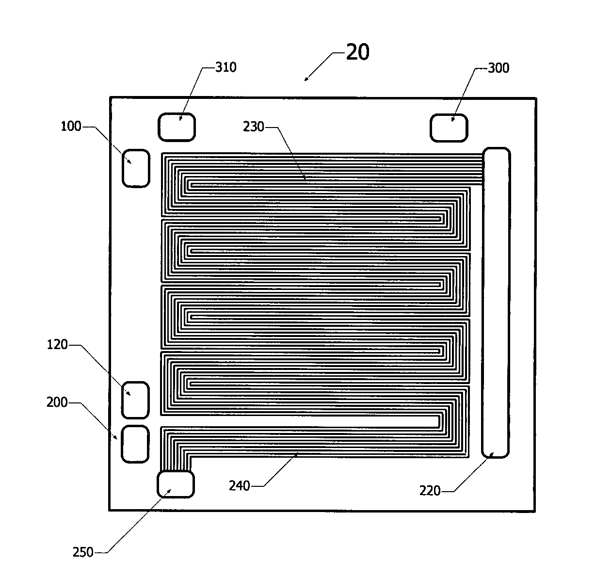
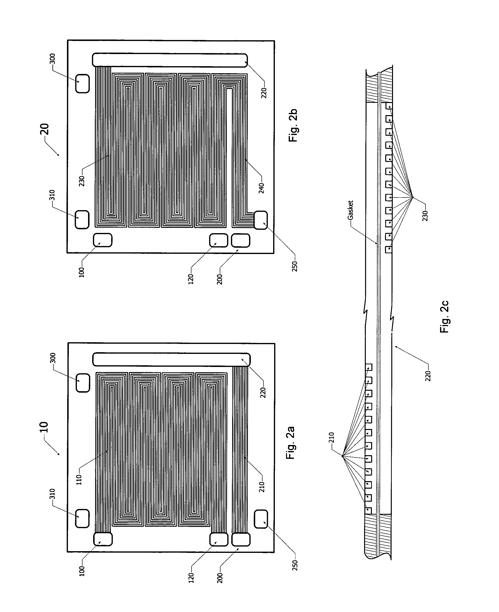
[0040] Throughout the description, the term “membrane electrode assembly” (MEA) will be understood as consisting of a solid polymer electrolyte or ion exchange membrane disposed between two electrodes formed of porous, electrically conductive sheet material, typically fiber paper but not limited thereto. The MEA contains a layer of catalyst, typically in the form of platinum, at each membrane / electrode interface to induce the desired electrochemical reaction. Suitable MEA materials can include those commercially available from 3M, W. L. Gore and Associates, DuPont and others. For the present invention, a portion of the membrane facing each plate is non-catalytic, water permeable, and gas impermeable in order to allow humidity exchange between fluid streams flowing through the humidification area of the cathode plate and the humidification area of the anode plate. Preferably, the water permeable membrane is impermeable to the reactant gases to prevent reactant portions of the supply ...


PUM


Abstract

A fuel cell plate integrating an active flow field zone for carrying out electrochemical reaction and at least one humidification zone for humidifying reactant stream. The area of the humidification field is proportionally designed to the fuel cell active flow field so that an adequate humidity and temperature can be achieved for fuel cell systems that can have different capacities, under which resizing the humidifier would be otherwise required by the prior art designs.

Description

CROSS-REFERENCE TO RELATED APPLICATIONS [0001] The application is related to commonly assigned co-pending U.S. patent application titled “Flow Field Plate for Use in Fuel Cells”, bearing agent docket number 16961-1US, the content of which is hereby incorporated by reference. The application is also related to commonly assigned co-pending U.S. patent application titled “Fuel Cell Stack with Even Distributing Gas Manifolds”, bearing agent docket number 16961-2US, the content of which is hereby incorporated by reference.TECHNICAL FIELD [0002] The invention relates -to proton exchange membrane (PEM) fuel cells. Particularly, this invention relates to a humidification method and device to conduct moisture and heat exchange between humid cathode exhaust air and incoming dry air and / or fuel. BACKGROUND OF THE INVENTION [0003] Proton exchange membrane fuel cells (PEMFCs) have received considerable attention lately as the primary low-temperature power generation devices useful in particular ...

Claims


Application Information

Patent Timeline
IPC IPC(8): H01M8/02H01M2/08
CPCH01M8/0258H01M8/0263Y02E60/50H01M2008/1095H01M8/04126H01M8/2483H01M8/0267H01M8/0276H01M8/04149
Inventor BAI, DINGRONGCHOUINARD, JEAN-GUYELKAIM, DAVID
Owner HYTEON
Why Eureka
Try Eureka