Stable power supplying apparatus

a power supply and apparatus technology, applied in emergency power supply arrangements, secondary cells servicing/maintenance, electrochemical generators, etc., can solve the problems of increasing power loss, short circuit or ground fault, and exceeding several minutes, and achieves low loss, light weight, and compact size.

Inactive Publication Date: 2006-01-19
THE KANSAI ELECTRIC POWER CO
View PDF3 Cites 32 Cited by
  • Summary
  • Abstract
  • Description
  • Claims
  • Application Information

AI Technical Summary

Benefits of technology

[0010] The present invention purposes to realize a stable power supply apparatus capable of supplying power significantly exceeding the power in normal time at the time of an instantaneous drop or an instantaneous pow

Problems solved by technology

A short circuit or a ground fault may occur in a rare case when a small animal, such as a snake or a bird, is caught on power transmission lines or when trees make contact with power transmission lines.
In this case, an “instantaneous drop” of a relatively long time, exceeding several minutes, may occur.
However, providing a large converter having rated power several times the

Method used


Image

  • Stable power supplying apparatus
  • Stable power supplying apparatus
  • Stable power supplying apparatus

Examples


first embodiment

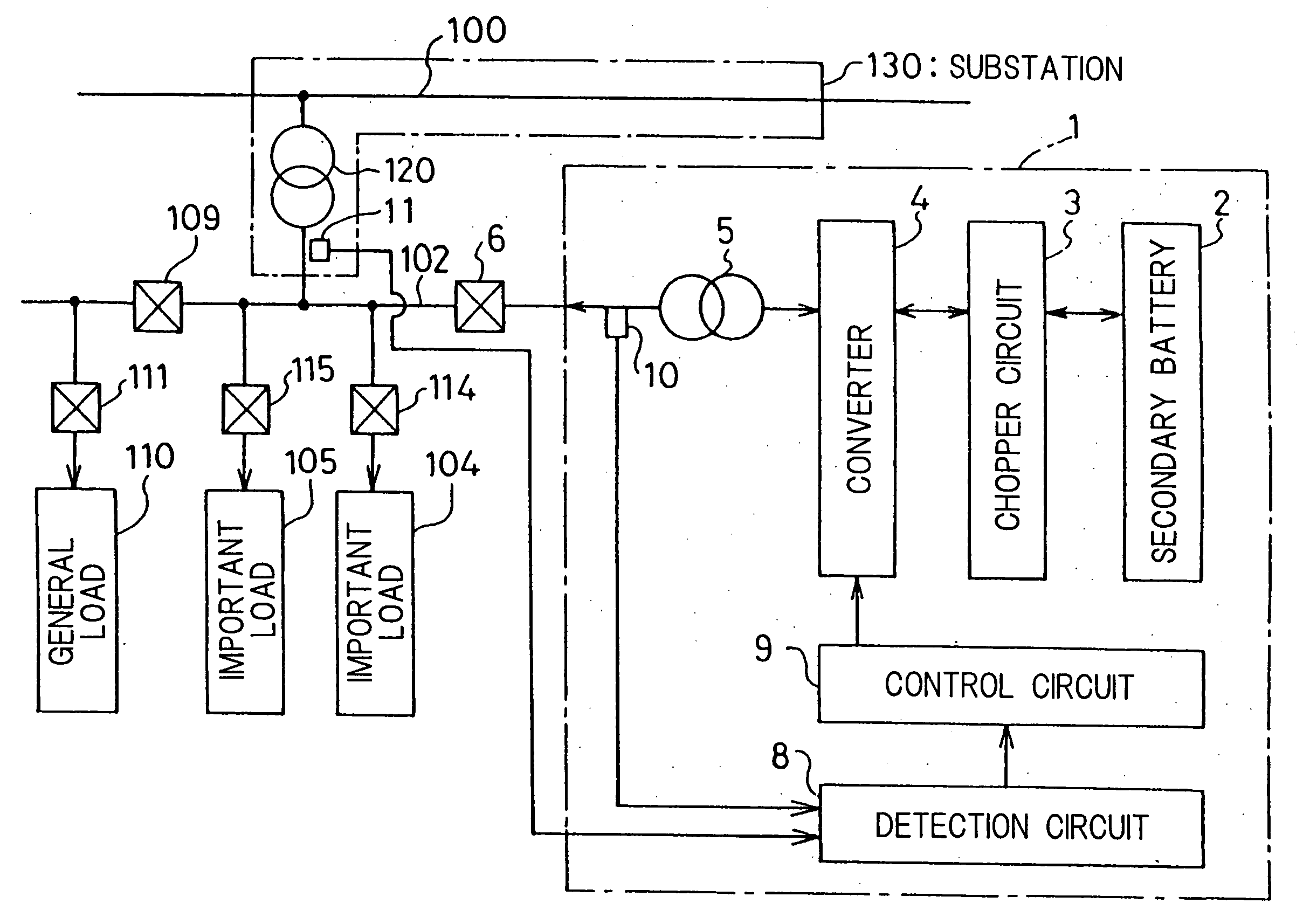
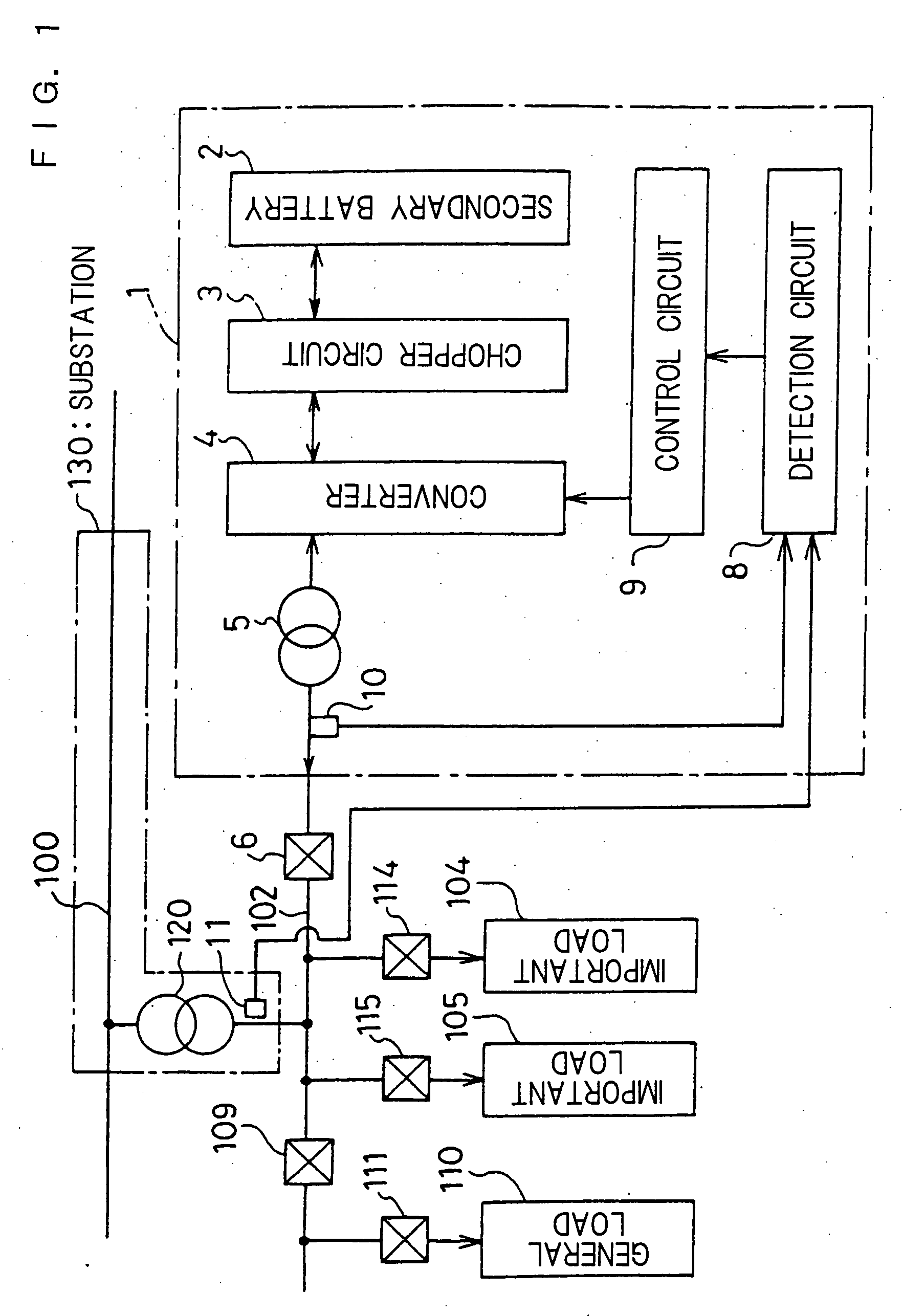
[0060]FIG. 1 is a block diagram of a stable power supply apparatus 1 for peak cut in accordance with a first embodiment of the present invention and a power supply system, to which the stable power supply apparatus 1 is connected, from a substation 130 to important loads 104 and 105 and an instantaneous (Sic) load 110. “Peak cut” is defined as supplying an excess amount from a power supply other than the substation 130 when power consumption exceeds the power that can be supplied from the substation 130, and the period in this state is referred to as “peak cut time.” In addition, the period in states other than the state of the peak cut time is referred to as “normal time.” In the figure, a system bus line 102 is connected to the power system 100 of the substation 130 via a transformer 120. To the system bus line 102, particularly important loads 104 and 105 are connected via switches 114 and 115, respectively. Furthermore, a general load 110, less important than the important loads...

second embodiment

[0070]FIG. 4 is a block diagram of a stable power supply apparatus 21 for load leveling in accordance with a second embodiment of the present invention. The stable power supply apparatus 21 has a secondary battery 22 formed of a sodium sulfur battery having a rated voltage of 1.5 kV and a rated power of 1.5 MW, a bidirectional chopper circuit 23, a converter 24 and a transformer 25, and is connected to a system bus line 102 of a voltage of 6.6 kV via a switch 6, like the stable power supply apparatus 1 shown in the above-mentioned FIG. 1. The other configurations are the same as those of the stable power supply apparatus 1.

[0071]“Load leveling” designates that power is stored during a low power demand time zone and the power is discharged during a high power demand time zone to deal with a phenomenon wherein power demand becomes significantly different depending on the time zone of the day. The switching device of the chopper circuit 23 is an anode-gate-type SiC-GTO having a voltag...

third embodiment

[0075]FIG. 5 is a block diagram of a stable power supply apparatus 31 for use in frequency fluctuation suppression in accordance with a third embodiment of the present invention. The stable power supply apparatus 31 has a secondary battery 32 using a redox flow battery having a voltage of 800 V and a rated power of 700 kW, a bidirectional chopper circuit 33, a converter 34 having a rated power of 600 kW and a transformer 35, and is connected to the system bus line 102 of a voltage of 6.6 kV via the switch 6 shown in FIG. 1. The other configurations are the same as those shown in FIG. 1.

[0076]“Frequency fluctuation suppression” designates to maintain the frequency at a rated value by adjusting the power supply using another power supply to prevent the frequency of AC of the power system 100 from being deviated from the rated value (50 Hz or 60 Hz) due to abrupt change in power demand. The switching devices of the chopper circuit 33 and the converter 34 are anode-gate-type SiC-GTOs h...


PUM


Abstract

A stable power supply apparatus in accordance with the present invention comprises a secondary battery, a bidirectional chopper circuit and a bidirectional converter, wherein the secondary battery, the chopper circuit and the converter are connected in this order in the direction from the secondary battery side to a system bus line side. The converter is formed of a wide-gap semiconductor device, more particularly, a wide-gap bipolar semiconductor device, and the instantaneous large-power operation capability of the wide-gap bipolar semiconductor device and the instantaneous large-power supplying capability of the secondary battery are utilized. For a short time during which the influence of an instantaneous drop is prevented, the converter is operated as a converter having capability exceeding the instantaneous large-power supplying capability of the secondary battery and having power capacity several times or more the rating of the converter.

Description

BACKGROUND OF THE INVENTION [0001] The present invention relates to a stable power supply apparatus connected to a power system, and more particularly to a stable power supply apparatus utilizing a secondary battery, such as a redox flow battery, a sodium sulfur battery or a lead-acid battery. [0002] In recent years, electronic apparatuses which are sensitive to fluctuations in a power supply voltage, such as personal computers and precision electronic apparatuses equipped with precision motors, have been used frequently. Hence, the need for countermeasures against an instantaneous voltage drop (hereafter simply referred to as an instantaneous drop), a phenomenon wherein the power supply voltage lowers significantly for a short time, is growing, and demand for stable power supply apparatuses serving as instantaneous voltage drop countermeasure apparatuses is increasing. In addition, it is required to add an instantaneous voltage drop countermeasure function to various kinds of stabl...

Claims


Application Information

Patent Timeline
IPC IPC(8): H01M10/46
CPCH01M10/42H02J9/062H01M10/425Y02E60/10
Inventor SUGAWARA, YOSHITAKA
Owner THE KANSAI ELECTRIC POWER CO
Why Eureka
Try Eureka