
Electrophotographic photoreceptor, process cartridge and electrophotographic apparatus

Active Publication Date: 2006-01-19
XEROX CORP +1
View PDF40 Cites 25 Cited by
  • Summary
  • Abstract
  • Description
  • Claims
  • Application Information

AI Technical Summary

Benefits of technology

[0034] The reasons for the advantageous effects of the invention is yet to be understood, but the inventors assume as followings:
[0035] A thickened undercoat layer containing metal oxide particles was effective in preventing leakage even when the electrophotographic photoreceptor is damaged with foreign substances derived from other members around the electrophotographic photoreceptor or dusts brought in from outside of the electrophotographic apparatus, but not effective in retaining the favorable electrical properties during long-term use. It seems that electric charges are accumulated in the undercoat layer or at the vicinity of the interface between the undercoat and upper layers during long-term repeated use.
[0036] If the undercoat layer contains an electron acceptor compound having a group reactive with metal oxide particles, the electron acceptor compound, which is reacted with and bound to the metal oxide fine particles in the undercoat layer, aids the charge transfer at the interface between the undercoat and upper layers and also prevents entrapment of electric charges in the undercoat layer, thus suppressing increase in the residual electric potential thereof during long-term use.
[0037] Hereinafter, favorable embodiments of the invention will be described in detail occasionally with reference to drawings. In the drawings, identical numbers are allocated to the same or similar parts, for elimination of duplicated description. (Electrophotographic Photoreceptor)
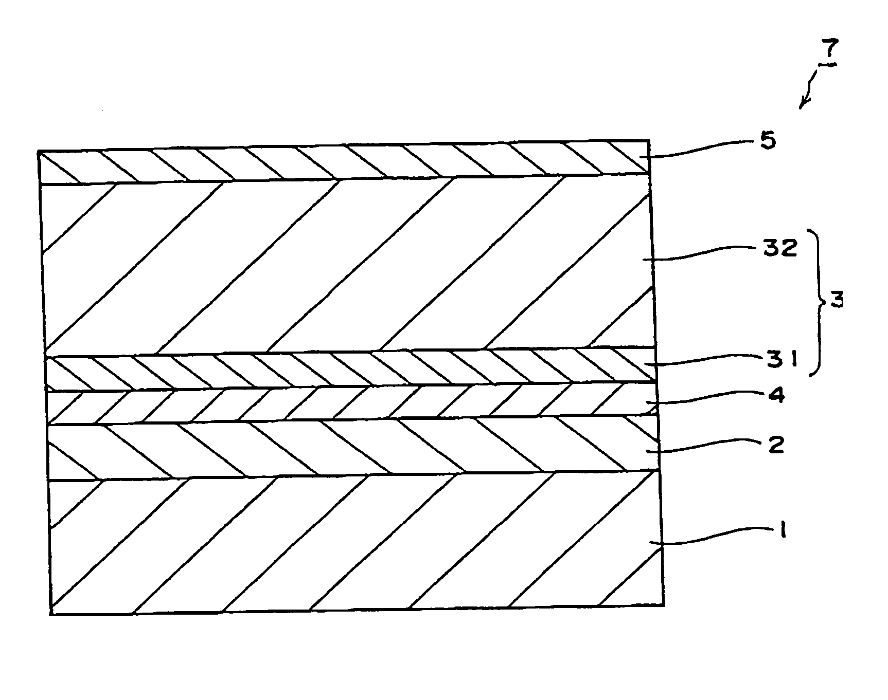
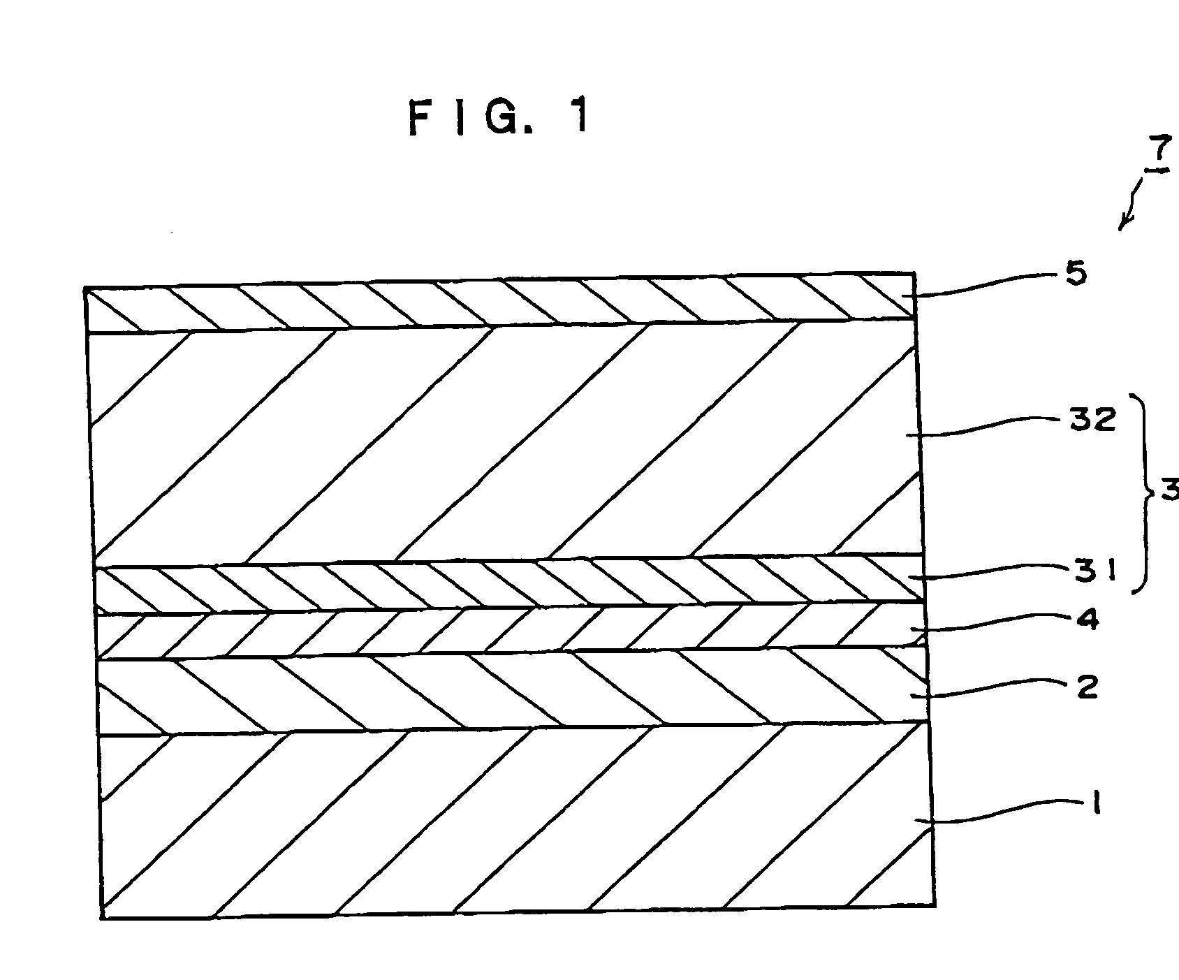
[0038]FIG. 1 is a schematic sectional view illustrating an example of the electrophotographic photoreceptor according to the invention. The electrophotographic photoreceptor 7 has a structure in which an undercoat layer 2, an intermediate layer 4, a photosensitive layer 3 and a overcoat layer 5 are laminated in that order on a conductive substrate 1. The electrophotographic photoreceptor 7 shown in FIG. 2 is a functionally separated layered photoreceptor, in which the photosensitive layer 3 further contains a charge-generating layer 31 and a charge-transporting layer 32.
[0039] Examples of the conductive substrates 1 include metal drums of metals such as aluminum, copper, iron, stainless steel, zinc, and nickel; base materials such as sheet, paper, plastic, and glass deposited with a metal such as aluminum, copper, gold, silver, platinum, palladium, titanium nickel chromium, stainless steel, copper, or indium, and with a conductive metal compound such as indium oxide, tin oxide, or the like; the base materials above laminated with a metal foil; conductive substrates above coated with a dispersion of carbon black, indium oxide, tin oxide, antimony oxide powder, metal powder, copper iodide or the like in a binder resin; and the like.

Problems solved by technology

In particular, in electrostatic charging devices using a contact charging process, which generate a smaller amount of ozone and are thus recently in electrophotographic apparatuses enjoying wider use in place of corotron-charging devices, electrical pinholes are often generated by a locally high electric field applied onto locally degraded areas of the electrophotographic photoreceptor during contact charging, leading to occasional image quality defects.
The pinhole leak is not only caused by the defects of coated films on an electrophotographic photoreceptor itself as described above, but also by conductive foreign substances generated in an electrophotographic apparatus, which come into contact with or penetrate into the electrophotographic photoreceptor, forming conductive paths between the contact-type electrostatic charging device and the electrophotographic photoreceptor substrate.
In some special cases, foreign substances derived from other members of the electrophotographic apparatus and dust brought into the electrophotographic apparatus generate leak points from the contact-type electrostatic charging device, by sticking into the electrophotographic photoreceptor.
However, the latter kind of undercoat layer, which demands both the resistance-adjusting and charge injection-controlling functions in a single undercoat layer, imposes a significant restriction on material design.
In addition, for leak prevention, a thicker undercoat layer is more effective and thus a film having a thickness of 10 μm or more is demanded; but if the resistance of a thick film is reduced for obtaining favorable electrical properties, it tends to have a deteriorated charge-blocking property and an increase in background fog as an image quality defect.
However, even with these methods, it is impossible to obtain a thickened undercoat layer that satisfies all the requirements for electrophotographic photoreceptors such as the improved leakage resistance, stabilized electrical properties, and low background fog.

Method used


Image

  • Electrophotographic photoreceptor, process cartridge and electrophotographic apparatus
  • Electrophotographic photoreceptor, process cartridge and electrophotographic apparatus
  • Electrophotographic photoreceptor, process cartridge and electrophotographic apparatus

Examples


example 1

[0238] A mixture of 100 parts by weight of zinc oxide (manufactured by Tayca Corporation, average particle diameter 70 nm, specific surface area: 15 m2 / g) and 500 part by weight of tetrahydrofuran is stirred; 1.25 parts by weight of a silane coupling agent (KBM603: manufactured by Shin-Etsu Chemical) is added thereto; and the mixture is stirred for 2 hours. Then, tetrahydrofuran is evaporated under reduced pressure; and the residue is baked at 120° C. for 3 hours, to give a zinc oxide pigment with the surface thereof treated with the silane-coupling agent.

[0239] A mixture of 38 parts by weight of a solution of 60 parts by weight of the surface-treated zinc oxide pigment, 0.6 part by weight of alizarin, 13.5 parts by weight of a hardening agent of a blocked isocyanate (Sumidur 3173: manufactured by Sumitomo Bayer Urethane Co.), and 15 parts by weight of a butyral resin (BM-1: manufactured by Sekisui Chemical Co.) in 85 parts by weight of methylethylketone and 25 parts by weight of m...

examples 2 to 4

[0243] Electrophotographic photoreceptors are prepared in a similar manner to EXAMPLE 1, except that the metal oxide surface-treated with a silane coupling agent and the electron acceptor compound used in EXAMPLE 1 are replaced with the compounds shown in Table 1, and the performance thereof is evaluated. Results are summarized in Table 11.


PUM


Abstract

An electrophotographic photoreceptor comprising: an electrophotographic photoreceptor having at least an undercoat layer and a photosensitive layer formed on a conductive substrate, wherein the undercoat layer contains metal oxide fine particles and an electron acceptor compound having a group reactive with the metal oxide fine particles. A process cartridge and an electrophotographic apparatus using the electrophotographic photoreceptor are also provided.

Description

CROSS-REFERENCE TO RELATED APPLICATON [0001] This application claims priority under 35 USC 119 from Japanese Patent Application No. 2004-210749, the disclosure of which is incorporated by reference herein. BACKGROUND OF THE INVENTION [0002] 1. Field of the Invention [0003] The present invention relates to an electrophotographic photoreceptor for use in image forming by an electrophotographic process, and a process cartridge and an electrophotographic apparatus using the electrophotographic photoreceptor. [0004] 2. Description of the Related Art [0005] Electrophotographic processes, which allow high-speed and high-quality printing, have been used in various electrophotographic apparatuses such as copying machines, laser beam printers, and the like. [0006] Mainstream electrophotographic photoreceptors used in electrophotographic apparatuses use an organic photoconductive material, and the performance of the photoreceptors has been improved as more electrophotographic apparatuses adopt...

Claims


Application Information

Patent Timeline
IPC IPC(8): G03G5/14
CPCG03G5/0696G03G5/144G03G5/142
Inventor NUKADA, HIDEMINAKAMURA, HIROFUMIQL, YUHU, NAN-XINGHOR, AH-MEEBANDO, KOJI
Owner XEROX CORP
Learn More