

High rate etching using high pressure F2 plasma with argon dilution
a plasma and high-pressure technology, applied in chemical vapor deposition coatings, coatings, coatings, etc., can solve the problems of nf3 plasma not being ignited above approximately 20 torr, nf3 plasma cannot be deposited and accumulate on the interior walls of the vacuum chamber, and the typical 10-kilowatt rps system cannot be achieved
- Summary
- Abstract
- Description
- Claims
- Application Information
AI Technical Summary
Benefits of technology
Problems solved by technology
Method used
Image

Examples
experiment 1
g Limits
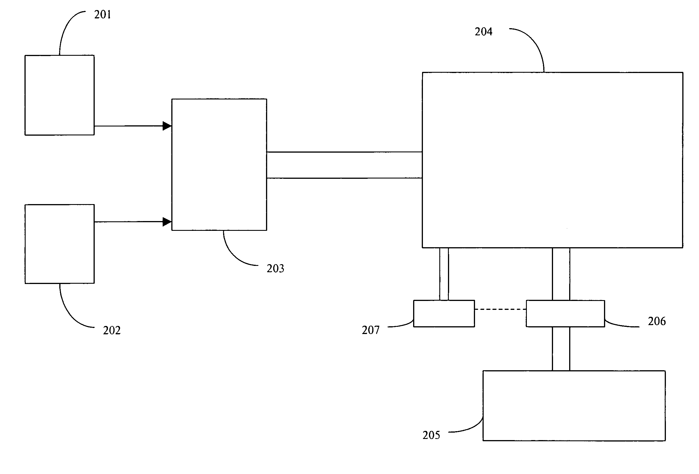
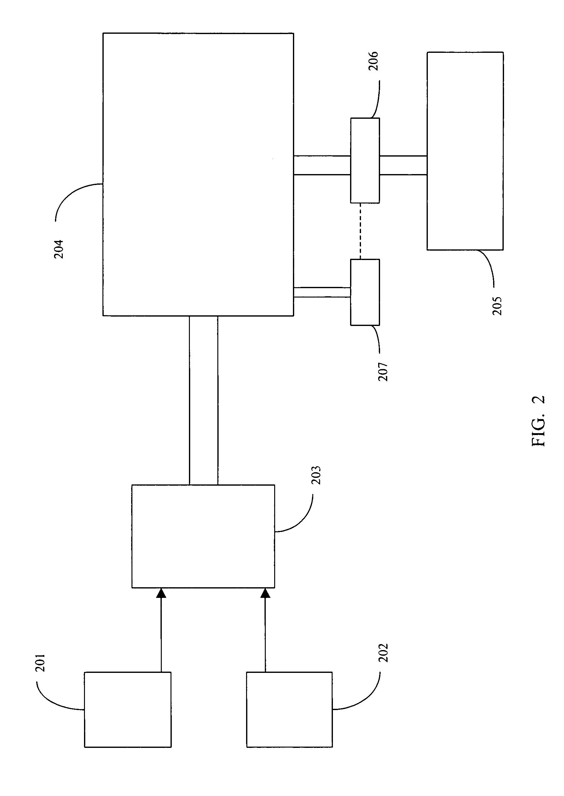
[0055] A vacuum system was assembled consisting of a NW40 4 way cross, the bottom of which was connected to a NW 100 spool piece packed with nickel, a vacuum control valve, a NW100 flexible spool piece and a BOCE Edwards QDP 80 / 500 dry pump. Connected to the left inlet of the 4 way cross was the outlet of an MKS Astronex remote plasma source. On the inlet side of the Astronex was an MFC controlled source of Ar and either NF3 or F2. Installed on top of the 4 way cross was a pressure transducer and on the left hand side a viewport.
[0056] A controlled flow of Ar was established and the plasma ignited. A set flow rate of source gas (NF3 or F2) was established and the Ar flow discontinued. The pressure in the system was set with the vacuum control valve from base to some maximum value. At regular intervals and at planned pressures the power drawn from the RPS (kW) was measured and recorded with a Fluke Model 41B power analyzer. When pressures caused the maximum power of the RPS ...
experiment 2
mparisons
[0058] The apparatus described in Experiment 1 was used, except that the 4 way cross was replaced with a 6 way cross. A removable, water-cooled, wafer chuck was installed on one port. The chuck was designed to hold small samples of wafers coated with 2 um SiO2. Installed in the opposite port was a viewport. A simple laser interferometer was directed through this port to measure the etch rate. Flows and pressure were manipulated as outlined below and etch rates were measured and recorded in the following manner. A laser of wavelength 670 nm strikes the SiO2 layer and reflects off the top of the layer and the bottom. Depending upon the phase of the reflected light the two beams will either reinforce or cancel each other. As the etch process causes the SiO2 layer to get thinner the signal from the detector will go through peaks and troughs. Measuring the time between peaks or troughs will give an etch rate in nm / s, with each wavelength representing a ˜335 nm change in thicknes...
experiment 3
[0060] During optimization etch rates were compared in relative terms. The etch rate corresponding to 100% was set as the slowest etch rate observed for all runs, which corresponds to standard run #2 for NF3 where pressure was set to 5.5 Torr and Ar / NF3 ratio to 3. The results of the optimization experiments are shown in Tables 3, 4 and 5.
TABLE 3NF3 OptimizationRelative EtchStandard RunAr / NF3 RatioPressure (Torr)Rate (% of run 2)105.5127.5235.51003020442.74320868.25012.75304.46312.75358.771.55.512781.520603.191.512.75303.6101.512.75460.6111.512.75327.8121.512.75373.4131.512.75316.1
[0061]
TABLE 4F2 OptimizationRelative EtchStandard RunAr / NF3 RatioPressure (Torr)Rate (% of run 2)105209.5245185.33050361.244501264.35027.5361.26427.5528.4725169.48250863.49227.5459.710227.5459.711227.5680.812227.5737.513227.5643.6
[0062]
TABLE 5Optimal Etch RatesAr / SourceSource GasGas RatioPressure (Torr)Relative Etch RateNF3 (optimal)320825NF3 (RPS limit)317.5679F2 (optimal)4501208
[0063] Two results for N...
PUM
| Property | Measurement | Unit |
|---|---|---|
| pressures | aaaaa | aaaaa |
| pressure | aaaaa | aaaaa |
| diameter | aaaaa | aaaaa |
Abstract
Description
Claims
Application Information