[0009] The instant invention presents a new and improved confocal
fluorescence microscope. The new microscope has significant advantages relative to existing implementations of microscope confocal imagers. In common with previous confocal imagers the instant invention has the advantages relative to conventional wide-field and confocal fluorescence imagers. However, the instant invention also addresses the drawbacks of confocal technology in terms of cost and complexity, and provides significant savings in both due to the simplicity of the components and the
elimination of the need, for example, of the physical spatial filters such as pinholes or slits. The
system is also compatible with a wide range of micro well plates including thin-bottom 96, 386, and 1536-well plates, microscope slides, and can support for a wide range of fluorescent dyes.
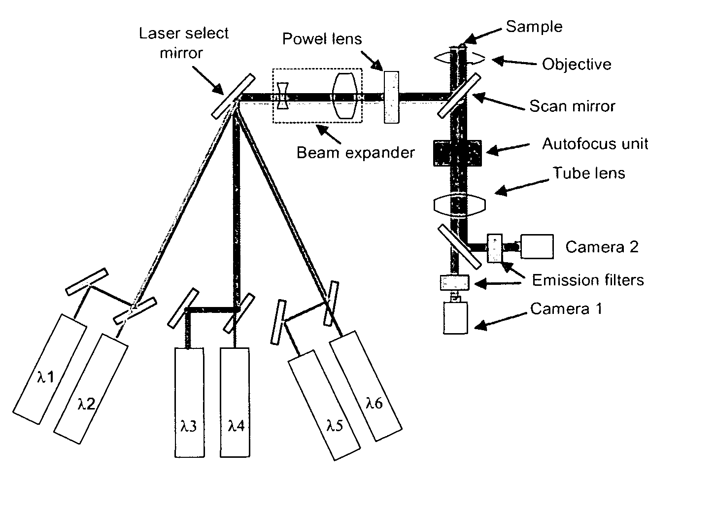
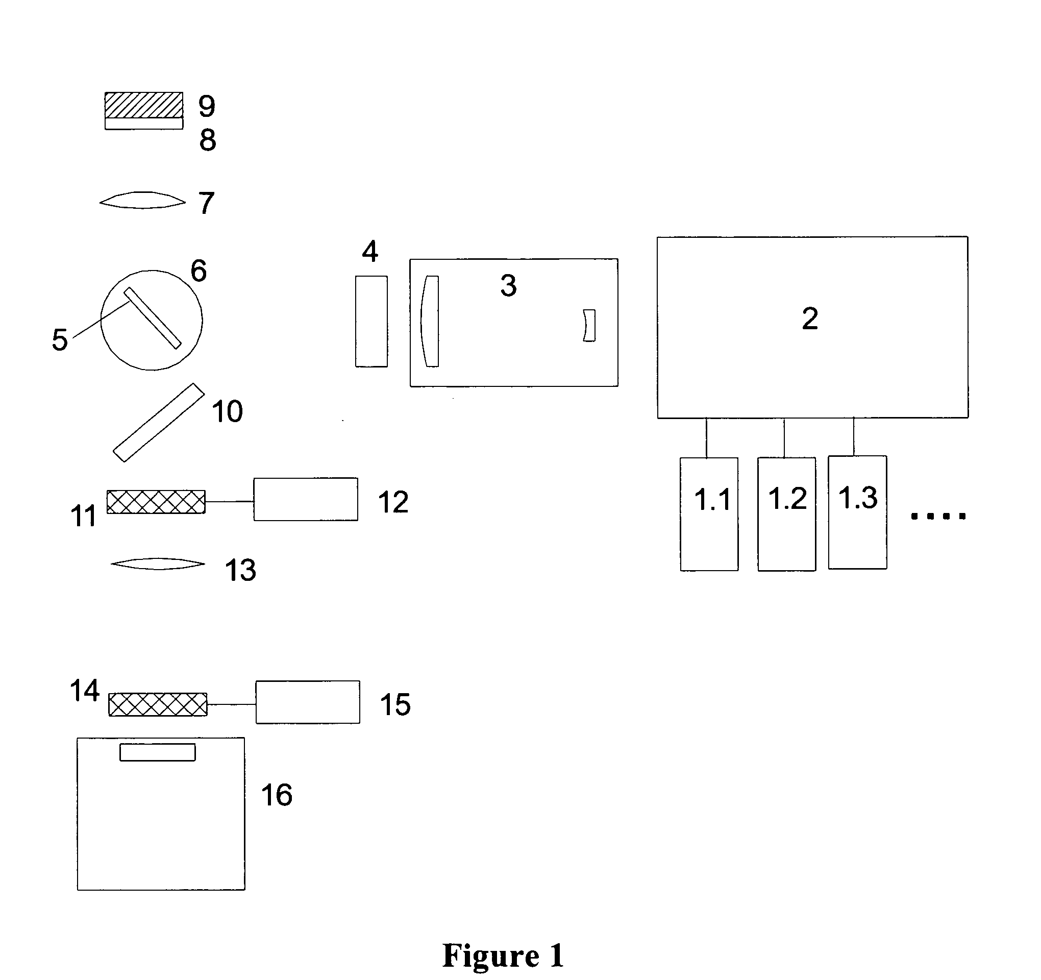
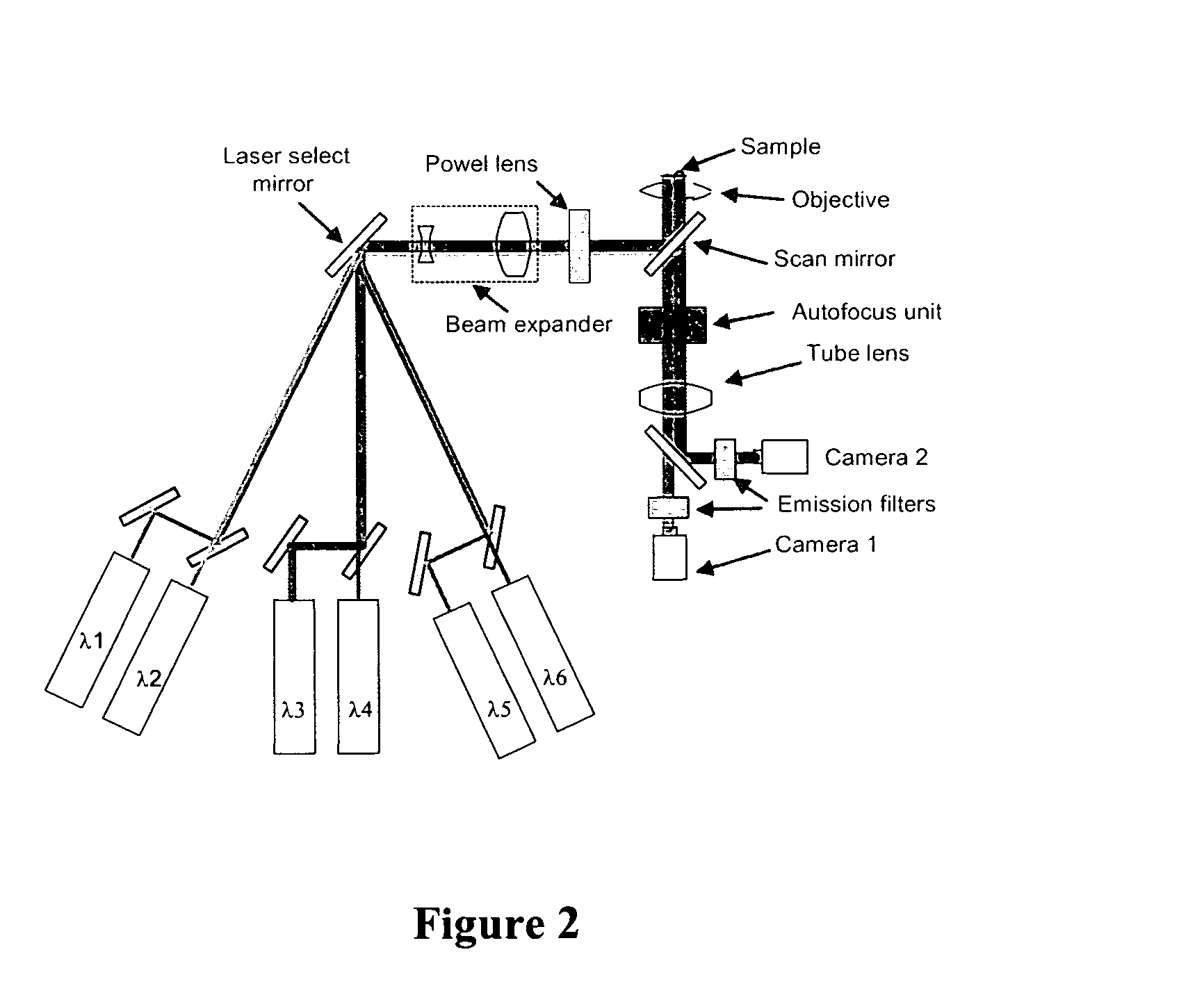
[0010] The
system comprises at least one, or more preferably two or more optical sources (preferably lasers) which will operate at different excitation wavelengths aligned with corresponding fluorescent or fluorescently stained or labelled targets. The fluorescent emission from each target is filtered using bandpass optical filters and the emission data is collected by at least one imaging device, preferably two or more imaging devices. The system presents certain distinct advantages over the prior wide-field fluorescence microscopes described above, including improved
image quality and increased sensitivity. More specifically, in ordinary fluorescence microscopy, emission from the material above and below the focal plane fluoresces results in undesirable
background fluorescence. Conventional wide-field fluorescence microscopes do not provide effective suppression of this background and, consequently, such microscopes will produce a relatively small
signal from the target
cellular material which “rides-on-top” of, and is affected by, a larger background signal. For example, when a
microtiter plate with a biological sample is imaged by a
wide field fluorescence microscope, background from the clear plastic bottom of the well-plate and the media above the
cellular material will ordinarily be substantially greater than the signal of cellular material. Analysis of such images is routinely accomplished by estimating and then subtracting this background.
[0012] 1. The
statistical noise in the
signal of interest is increased as a result of the background. This reduces the ability to identify features of interest because such background fluorescence is typically responsible for >90% of the
noise in the image and must be corrected for by estimating the contribution of the
background noise. Further, because this
estimation involves certain assumptions, this complicates analysis and interpretation and it decreases the sensitivity of the system.
[0014] The use of a
confocal imaging microscope will typically suppress this background fluorescence by a factor of 20 to 100 relative to the fluorescence signal from the focal plane, thereby permitting a more accurate image to be obtained. However, confocal microscopes are often costly and complex to operate and use. The instant system reduces the cost and complexity of the system by introducing a simplified detection sub-system comprising one or more
detector capable of
random access for detecting the fluorescent emission. The
detector is preferably a low cost,
CMOS optical sensor which minimizes the contribution due to the
dark current to negligible, even when the sensor is operated at
room temperature, however other pixel-based detectors, such as appropriate CCD cameras can also be used. Suitable detection devices are described in
CMOS Imagers: From Phototransduction to
Image Processing, Orly Yadid-Pecht and Ralph Etienne-Cummings (Editors), Springer (Publisher), 1st editon (May 31, 2004), incorporated herein by reference.
[0018] In a further preferred embodiment, the line forming means is paired with a
CMOS detector that is operated in the
rolling shutter mode to produce a low cost, simple, and easy to use line confocal
scanner 

