Ion exchange regeneration and upw treatment system

a technology of ion exchange and upw treatment system, which is applied in the direction of water/sewage treatment by ion exchange, separation process, ion exchanger, etc., can solve the problems of presenting design problems of various types in the high-purity water system of the plant, and affecting the quality of the feed water

Active Publication Date: 2006-02-02
BL TECH INC
View PDF9 Cites 38 Cited by
  • Summary
  • Abstract
  • Description
  • Claims
  • Application Information

AI Technical Summary

Benefits of technology

[0023] A water treatment system of the invention may employ a bed of boron-scavenging resin, such as boron chelating anion exchange resins based on glucamine or the like, and / or aggressively regenerated strong base anion exchange resin to substantially remove boron. Preferably one or more detectors monitor boron at relevant locations in the treatment system, e.g., samples water downstream or upstream of the resin bed, or a probe samples within the resin bed, for example toward a downstream end thereof or at the output of the upstream stage of a two-stage polisher. By sampling at least one point ahead of the final outlet, the detector is able to determine a profile of the remaining resin activity, and deduce the condition of the bed or the output quality of water treated by the bed, earlier or more accurately. By sampling upstream of the bed, one may determine a time / flow profile of remaining treatment capacity, may implement a predictive model of the boron uptake for scheduling resin replacement or regeneration, and may predict the output water quality and its suitability for different end uses.

Problems solved by technology

An in-plant high purity water system may present design problems of various types.
Beyond the factors of capital cost and operating expenses, and the environmental considerations raised by the volume of waste water and by-product of the contaminant-removal treatment processes, various unanticipated problems may arise.
Types or levels of contaminants in the feed water may change abruptly, necessitating changes in treatment protocols.
The periodically-performed process of regenerating an ion exchange bed, or the unanticipated fouling in the treatment line of a bed or membrane-based treatment system (an RO, ED or EDI unit), may destabilize or impair the treatment process or the quality of the output stream.
Even so, the continual introduction of new fabrication technologies requires plant operators to frequently ascertain whether existing water quality specs remain sufficient.
Indeed, an unrecognized or unexpected contaminant might impair the response of the detector, rather than simply passing undetected.
Production down time is quite costly, and the observation of unexplained defects or process variations raises the possibility of additional undetected latent defects, and the specter of defective manufactured products further down the manufacturing train.
However, problems may be encountered at this stage.
Spent resin from mixed bottles or beds must be separated into anion and cation exchange resins before regeneration, and the separation processes, typically relying on fluidized settling separation properties affected by density, bead size and the like are necessarily imperfect.
There is thus a possibility of introducing unanticipated contamination from other resins during various regen resin handling plant operations, e.g., conglomeration, separation by type, regeneration, rinsing, re-mixing and bottle filling.
The more weakly dissociated species are also captured with lower efficiency, and may extend diffusely along a relatively long depth of the ion exchange bed.
One group has reported, however, that the latter method resulted in the need for extremely frequent regeneration of the polish bed—over one hundred times per year.
Boron is loosely held, is easily displaced, and is captured with fairly low efficiency by the remaining downstream resin.
It appears therefore that at least some regeneration processes do not produce regenerated resin capable of sustained and dependable boron removal.

Method used


Image

  • Ion exchange regeneration and upw treatment system
  • Ion exchange regeneration and upw treatment system
  • Ion exchange regeneration and upw treatment system

Examples


Embodiment Construction

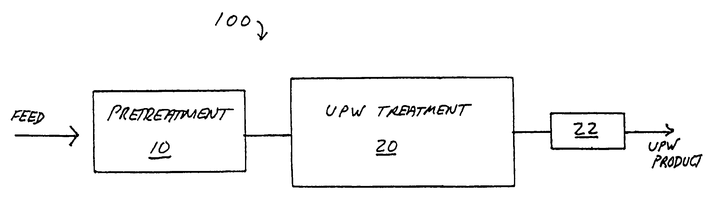
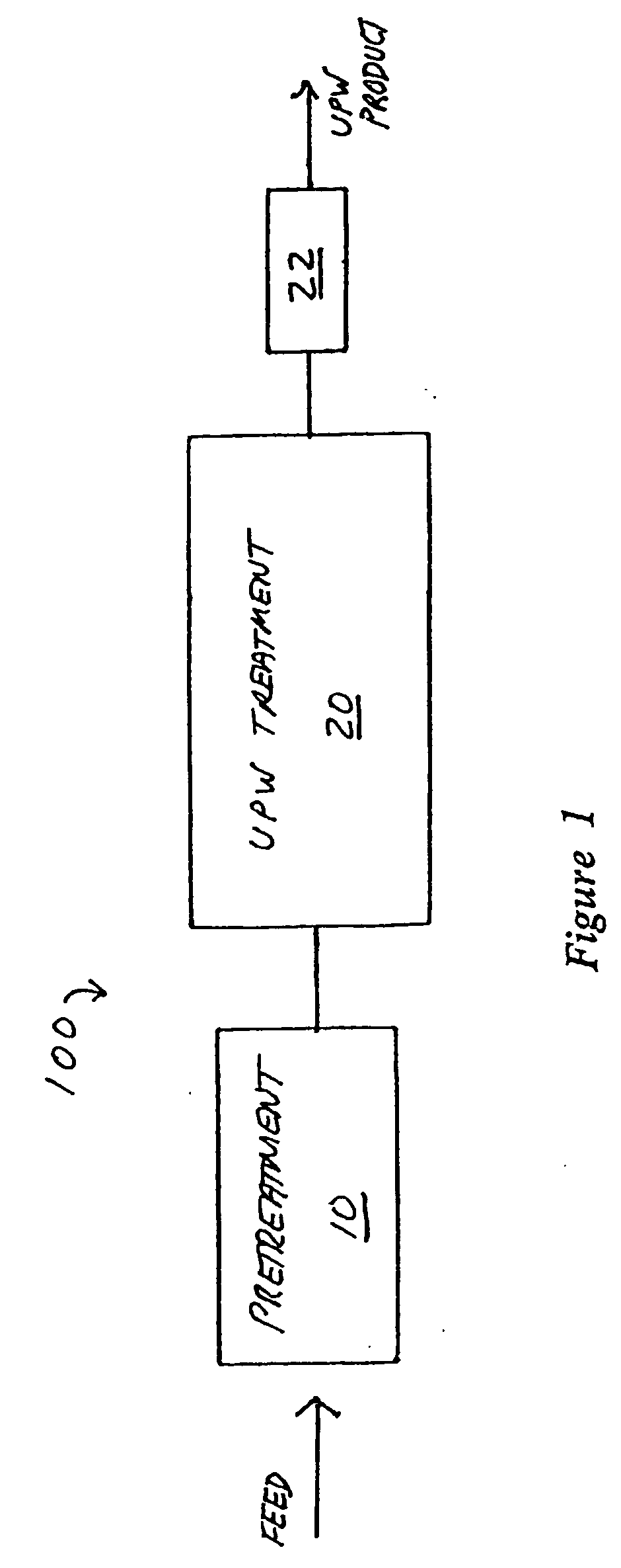
[0033]FIG. 1 schematically illustrates a water treatment plant 100, which may be conveniently viewed as a sequence of treatment or conditioning processes (not separately identified in the FIGURE) some in series and some in parallel that perform a pretreatment 10 followed by further treatment 20 to produce a product water substantially free of impurities, i.e., intrinsic water. The exact unit operations in treatment processes 10 and 20 may vary widely, depending upon the quality of the starting water or feed stream, and the desired quantity (recovery) and qualities of the high purity treated water, i.e., the product stream.

[0034] The pretreatment 10 may include processes that are carried out upstream in the supply, such as settling, flocculation and filtration to render the water suitable for later treatment stages, as well as processes such as sterilization, softening, pH adjustment or the like which may serve to address specific impurities or to enhance the stability, yield or ope...


PUM

PropertyMeasurementUnit
lengthaaaaaaaaaa
lengthaaaaaaaaaa
thresholdaaaaaaaaaa

Abstract

An improved process for regenerating ion exchange resin, includes a regeneration step of displacing captured ions from the resin to regenerate its ion-capture functionality, followed by one or more fluid-employing post-regeneration steps such as a fluid displacement or rinse, a fluid transport or mixing, and a rinse down to quality. To avoid problems of early leakage of weakly held ions such as boron, the post-chemical or postdisplacement steps use water that is essentially free of boron, or otherwise avoid localized contamination in the regenerated resin which is used in bottles or beds (30). A two-stage polish may be operated with modified lead/lag bottles. A detector (D) for an indicator condition (conductivity, silica breakthrough) between stages determines when to shift the lag bottle forward, and periodically both bottles are replaced.

Description

[0001] This invention relates to water purification and to ion exchange media. [0002] It also relates to methods for regenerating exchange media for use in providing ultrapure water for semiconductor fabrication or other processes requiring product water substantially free of impurities. [0003] It also relates to production of ultra pure water (UPW), and to sensing, control and maintenance in a water processing system that relies upon a measurement, such as a measurement of conductivity or the concentration of species in the feed or product stream, as an indicator or control parameter. BACKGROUND [0004] Many processes, such as semiconductor fabrication processes, require water to have an extremely low concentration of ionic and non-ionic impurities. A manufacturing or processing facility with such requirements generally establishes a dedicated water purification plant having suitable treatment capacity and impurity removal characteristics to meet its process requirements. Such a tre...

Claims


Application Information

Patent Timeline
Patent Type & Authority Applications(United States)
IPC IPC(8): C02F1/42B01J49/00
CPCB01J49/0004C02F1/42B01J49/0095B01J49/0078B01J49/05B01J49/60B01J49/85
Inventor CARSON, WILLIAMWDALE, CHARLESMCCLAIN, WILLIAMDRITZ, ROBERTSWENSON, CHARLES
Owner BL TECH INC
Why Eureka
Try Eureka