Circuitized substrate with internal organic memory device, method of making same, electrical assembly utilizing same, and information handling system utilizing same

a circuitized substrate and internal organic memory technology, applied in the direction of printed circuit aspects, instruments, semiconductor/solid-state device details, etc., can solve the problems of significant signal transmission concerns, significant signal behavior, and increased complexity of circuitized substrates such as pcbs, and achieve the effect of not affecting the cost of significant increas

Inactive Publication Date: 2006-02-02
I3 ELECTRONICS +1
View PDF18 Cites 29 Cited by
  • Summary
  • Abstract
  • Description
  • Claims
  • Application Information

AI Technical Summary

Benefits of technology

[0021] It is another object of the invention to provide a method of making such a substrate and internal organic memory device combination which can be accomplished utilizing many known PCB manufacturing processes and thus without a significant increase in the cost for making such a relatively complex final structure.

Problems solved by technology

This requires precision drilling to form the plated thru-holes (PTHs) all of which is time consuming, especially where there are a large number of drilled holes required to form PTHs.
Complexity of circuitized substrates such as PCBs has increased significantly over the past few years, due primarily to increased operational requirements for the products in which these substrates are utilized.
However, if the transmission line changes characteristic impedance at any point along the way, signal behavior becomes more complicated.
The reflections caused by these impedance mismatches have the ability to alter the original signal transmission, even possibly causing such problems as logic circuits to switch inadvertently.
Furthermore, as signal “rise times” drop below a certain level (in highly dense PCB structures, 1 nanosecond (ns)), PCB thru-holes, including the relatively short internal “vias” mentioned above, may possibly create large enough reflections as to potentially cause significant signal transmission concerns.
As such, most vias exhibit very low impedance and are a poor match to typical PCB traces.

Method used


Image

  • Circuitized substrate with internal organic memory device, method of making same, electrical assembly utilizing same, and information handling system utilizing same
  • Circuitized substrate with internal organic memory device, method of making same, electrical assembly utilizing same, and information handling system utilizing same
  • Circuitized substrate with internal organic memory device, method of making same, electrical assembly utilizing same, and information handling system utilizing same

Examples


Embodiment Construction

[0035] For a better understanding of the present invention, together with other and further objects, advantages and capabilities thereof, reference is made to the following disclosure and appended claims in connection with the above-described drawings. It is understood that like numerals will be used to indicate like elements from FIG. to FIG.

[0036] The following terms will be used herein and are understood to have the meanings associated therewith.

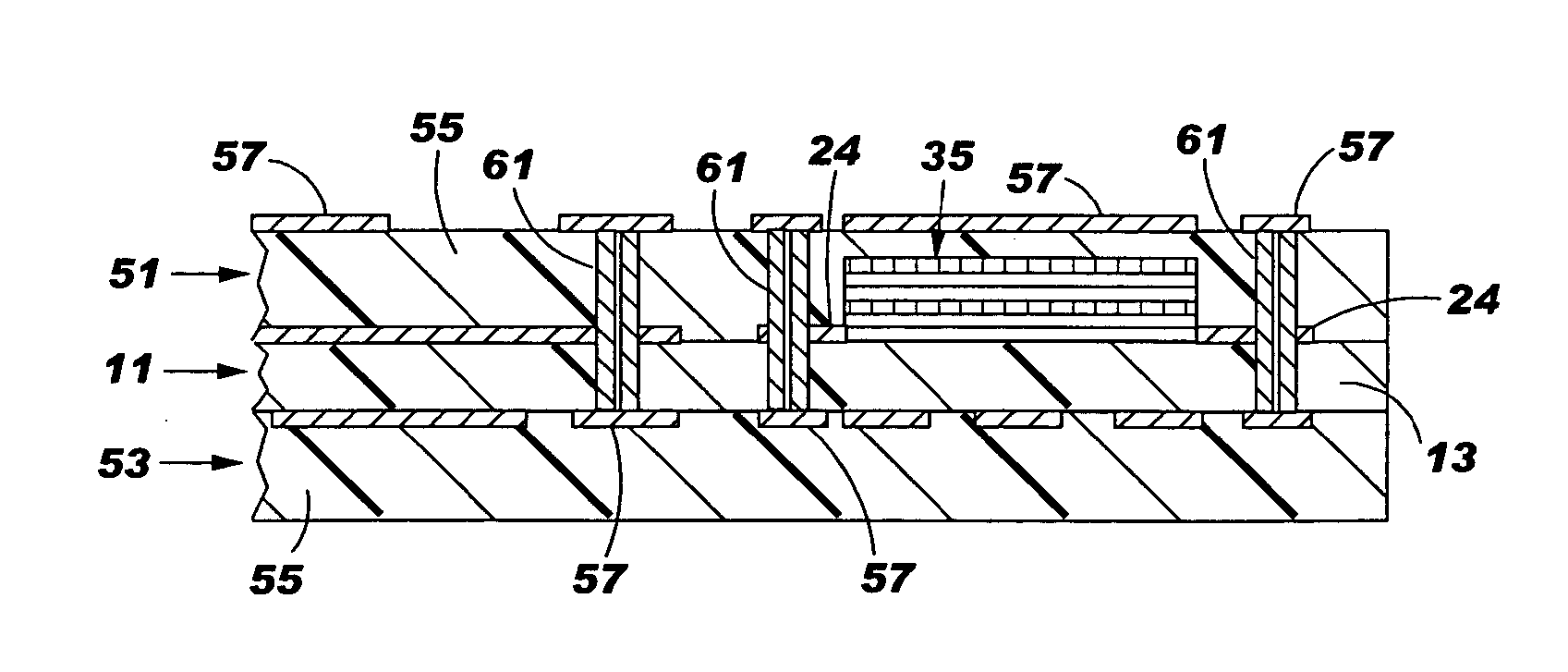
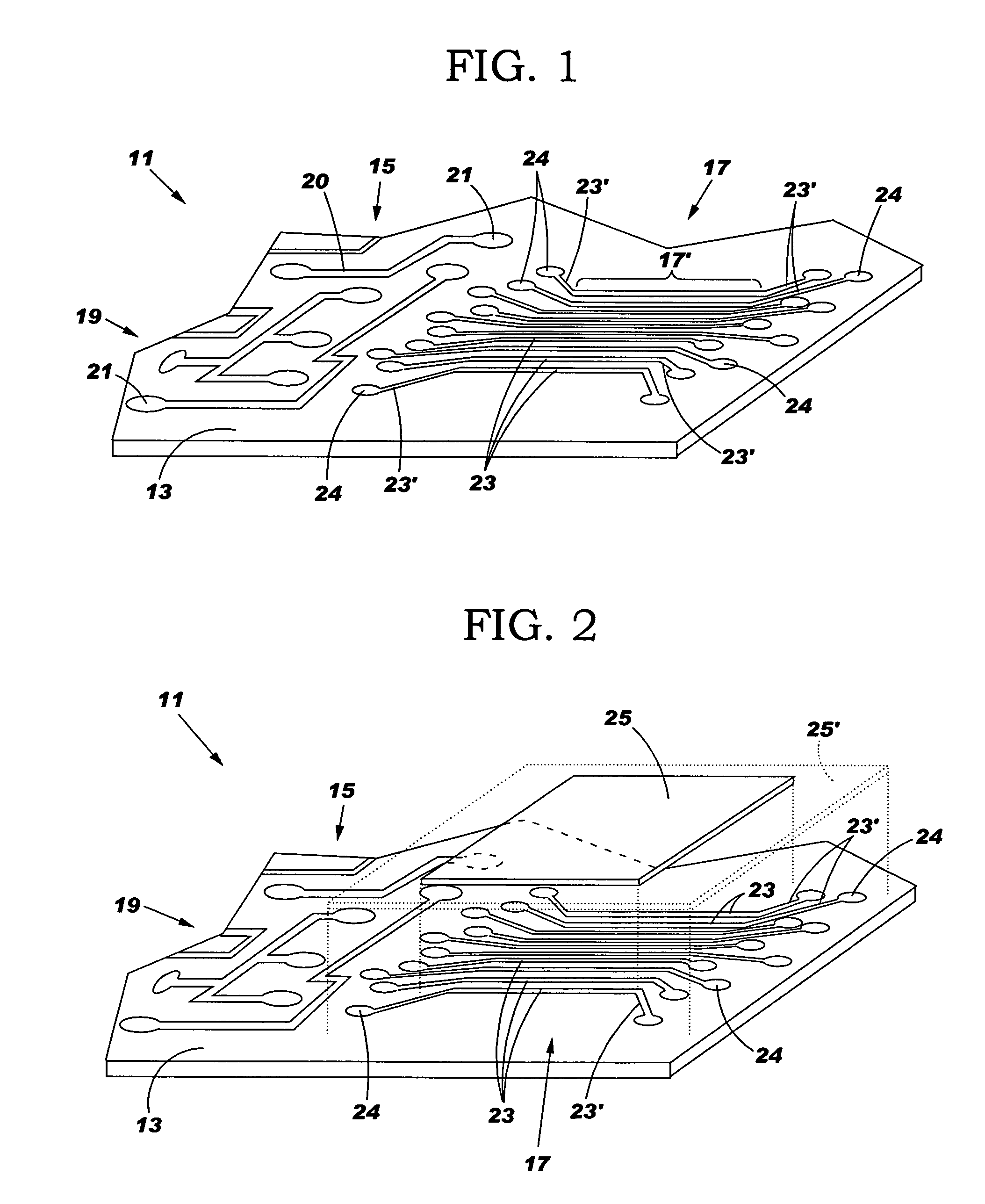
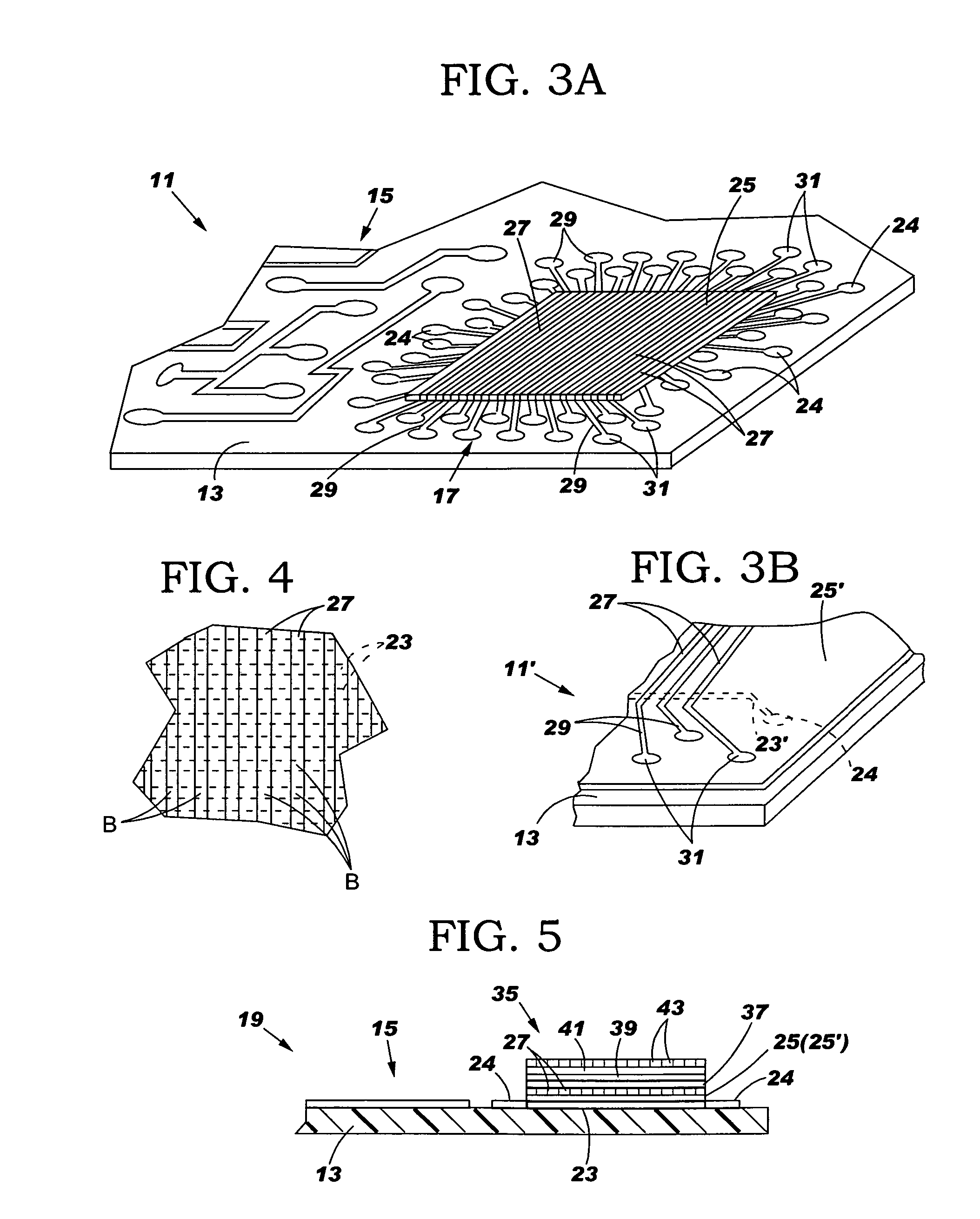
[0037] By the term “circuitized substrate” is meant to include substrates having at least one dielectric layer and one conductive layer. In many cases, such substrates will include several dielectric and conductive layers. Examples include printed circuit boards (PCBs) or like structures made of dielectric materials such as fiberglass-reinforced epoxy resins, polytetrafluoroethylene (Teflon), polyimides, polyamides, cyanate resins, photoimageable materials, and other like materials wherein the conductive layer is a metal layer (e.g., po...


PUM


Abstract

A circuitized substrate comprised of at least one dielectric material having an electrically conductive pattern thereon. At least part of the pattern is used as the first layer of an organic memory device which further includes at least a second dielectric layer over the pattern and a second pattern aligned with respect to the lower part for achieving several points of contact to thus form the device. The substrate is preferably combined with other dielectric-circuit layered assemblies to form a multilayered substrate on which can be positioned discrete electronic components (e.g., a logic chip) coupled to the internal memory device to work in combination therewith. An electrical assembly capable of using the substrate is also provided, as is an information handling system adapted for using one or more such electrical assemblies as part thereof.

Description

TECHNICAL FIELD [0001] The present invention relates to circuitized substrates, and more particularly to composite circuitized structures such as printed circuit boards (PCBs), chip carriers, and the like. The present invention also relates to methods for fabricating such structures, electrical assemblies (e.g., PCB-chip carrier assemblies) utilizing same, and to information handling systems (e.g., computers, servers, etc.) utilizing such substrates and / or assemblies. BACKGROUND OF THE INVENTION [0002] One known method of forming a laminate circuitized substrate (e.g., PCB) structure includes forming layers of dielectric material and electrically conducting material to provide multiple layers of circuits and voltage planes. Circuits can be discrete wiring patterns known as signal planes. Voltage planes can be either ground plane or power planes, and are sometimes collectively referred to as power planes. In one technique of forming such structures, layers of dielectric material and ...

Claims


Application Information

Patent Timeline
Patent Type & Authority Applications(United States)
IPC IPC(8): H01L29/00H01L21/00
CPCG11C11/22H01L2224/16H01L2224/73253H01L2924/01046H01L2924/01078H01L2924/01079H05K2201/10159H01L2924/16195H01L2924/3011H05K1/16H05K2201/0166H05K2201/0179H05K2201/09763H01L2924/15311H01L2924/00014H01L2924/00011H01L2224/0401
Inventor DESAI, SUBAHU D.LIN, HOW T.LAUFFER, JOHN M.MARKOVICH, VOYA R.THOMAS, DAVID L.
Owner I3 ELECTRONICS
Why Eureka
Try Eureka