High temperature ceramic lubricant

a ceramic lubricant and high temperature technology, applied in the direction of liquid fuel engines, superimposed coating processes, machines/engines, etc., can solve the problems of high cost of repair and/or replacement, high vibration of bushing and washer structures used in variable stator vanes, and wear of many structures in gas turbine engines, so as to improve resistance, reduce wear, and improve the effect of resistan

Inactive Publication Date: 2006-02-09
GENERAL ELECTRIC CO
View PDF99 Cites 34 Cited by
  • Summary
  • Abstract
  • Description
  • Claims
  • Application Information

AI Technical Summary

Benefits of technology

[0017] The variable stator vane assembly having a lubricant coating, according to the present invention, is subject to reduced wear while having an improved resistance to vibration and improved resistance to elevated temperatures, where the variable stator vane assembly may be utilized at temperatures greater than about 1000° F. (538° C.), including operational temperatures of greater than about 1200° F. (649° C.).
[0018] Another advantage of the lubricant coating, according to the present invention, is that the wear coating and antifriction coating combination reduces wear and maintains desirable tribological properties in high altitude atmospheres having little or no water vapor.
[0019] Another advantage of the lubricant coating, according to the present invention, is that the variable stator vane assembly provides an efficiency improvement in the turbine engine while reducing overhaul costs caused by wear resulting from metal on metal contact between the stator casing surface and the stator vane surface.
[0020] Another advantage of the lubricant coating, according to the present invention, is that the materials used in the variable stator vane assembly of the present invention, including the antifriction coating, can readily withstand the higher temperatures of operation utilized in current advanced engine designs. The materials used in the antifriction coating of the present invention can be utilized at temperatures greater than about 1000° F. (538° C.), including operational temperatures of up to about 1200° F. (649° C.), without significant deterioration due to the combined effects of temperature, vibration, and high altitude atmosphere.
[0021] Another advantage of the lubricant coating of the present invention is that the antifriction coating is capable of maintaining lubricity in applications that rub in a reciprocating motion.
[0022] Another advantage of the lubricant coating, according to the present invention, is that the antifriction coating is resilient and regenerates in areas where the antifriction coating is rubbed thin or cleaned off the wear surface.

Problems solved by technology

A number of structures in the gas turbine engine, including the bushing and washer structures, used with variable stator vanes are subjected to conditions of wear at temperatures ranging from low temperatures to highly elevated temperatures.
In addition, the bushing and washers are subject to high altitude atmospheres.
In the bushing and washer system of the variable stator vane assembly, scoring may occur on one or both of the surface of the trunnion and the casing, both of which are expensive to repair and / or replace.
As the surfaces are damaged, they become even more susceptible to the effects of wear as their effective coefficients of friction rise and wear increases the clearance between the wearing surfaces, so that the loads are more concentrated and causes undue motions, so the wear damage accelerates with increasing time in service.
Wear damage may include material, such as wear debris, removed from the wearing surfaces due to wear, or may include foreign particles, such as dust or debris from the air traveling through the engine.
The increased force requirement causes additional strain and possible failure of the actuator and / or results in the need for a larger actuator.
The wear conditions sometimes arise because it is not desirable or possible to firmly affix the two components together to prevent the rubbing action, because of the functionality of the components.
When a bushing and washer system fails due to excessive wear, serious problems for the gas turbine engine compressor may occur.
The failure of the bushing and washer may create an increase in leakage of compressed air from the interior of the compressor through the variable stator vane assembly, which results in performance loss for the compressor.
In addition, failure of the bushing and washer can result in contact between the stator vane and the casing, which causes wear and increases overhaul costs of the engine.
(316° C.) limit their operational life.
The polymer matrix bushings do not withstand the combinations of high temperature and vibrational loading experienced in the operation of the gas turbine engine well, leading to a relatively short part life.
However, graphite has the disadvantage that water vapor is required to maintain lubricity.
Atmospheres at aircraft cruise altitudes do not have enough water vapor present for graphite to be lubricious.
Graphite also has the disadvantage of poor tribological properties in applications that require reciprocating motion.
An additional disadvantage of graphite is that graphite begins to oxidize rapidly at temperatures at or greater than 500° C.
However, the single wear coating lacks the ability to maintain the properties of each of the individual components (i.e., fails to maintain both low coefficient of friction and wear resistance).
In other words, the single wear coating does not provide all of the desired tribological properties (e.g., reduced wear and low coefficient of friction) required for extended operation of variable stator vanes subject to conditions of high temperature, vibration and high altitude atmospheres.

Method used


Image

  • High temperature ceramic lubricant
  • High temperature ceramic lubricant
  • High temperature ceramic lubricant

Examples


Embodiment Construction

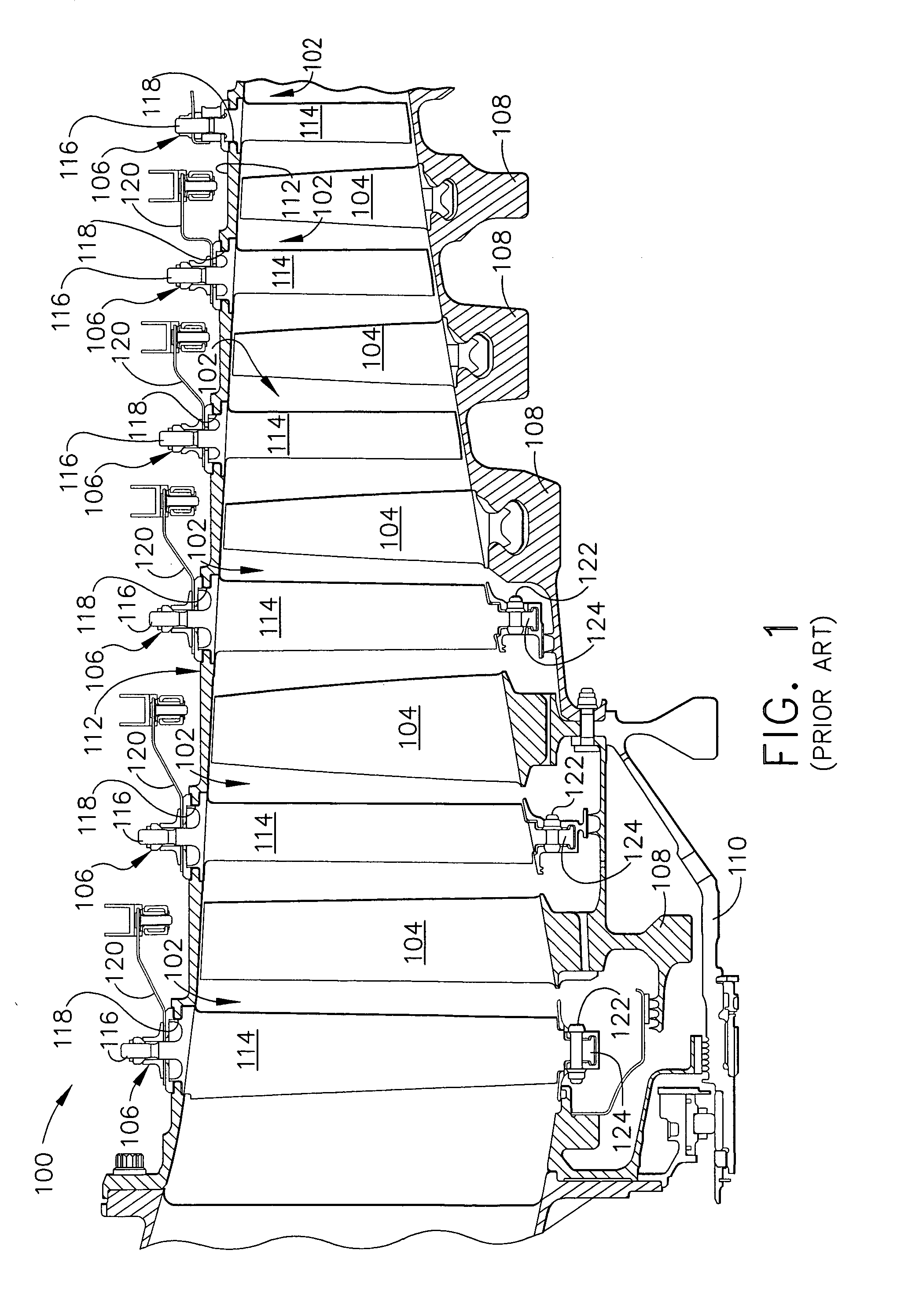
[0029]FIG. 1 is a schematic view of a section of a known high-pressure compressor 100 for a turbine engine (not shown). Compressor 100 includes a plurality of stages 102, and each stage 102 includes a row of rotor blades 104 and a row of variable stator vane assemblies 106. Rotor blades 104 are typically supported by rotor disks 108, and are connected to a rotor shaft 110. Rotor shaft 110 is a high-pressure shaft that is also connected to a high-pressure turbine (not shown). Rotor shaft 110 is surrounded by a stator casing 112 that supports variable stator vane assemblies 106.

[0030] Each variable stator vane assembly 106 includes a variable vane 114 and a vane stem 116. Vane stem 116 protrudes through an opening 118 in casing 112. Variable vane assemblies 106 further include a lever arm 120 extending from variable vane 114 that is utilized to rotate variable vanes 114. The orientation of variable vanes 114 relative to the flow path through compressor 100 control airflow therethroug...


PUM

PropertyMeasurementUnit
temperaturesaaaaaaaaaa
weight ratioaaaaaaaaaa
coefficient of frictionaaaaaaaaaa

Abstract

A gas turbine engine component having opposed surfaces in frictional contact with each other. An antifriction coating is disposed on one or more of the opposed surfaces. The antifriction coating includes a binder and a friction modifier. The weight ratio of the friction modifier to binder in the antifriction coating is greater than or equal to about 1:1.

Description

CROSS-REFERENCE TO RELATED APPLICATIONS [0001] This application is a Continuation-in-Part of U.S. patent application Ser. No. 11 / 015,936 filed on Dec. 17, 2004, claims priority to that application, which is herein incorporated by reference in its entirety, which is a continuation-in-Part of U.S. patent application Ser. No. 10 / 445,428 filed on May 27, 2003, which is herein incorporated by reference in its entirety.BACKGROUND OF THE INVENTION [0002] This invention relates generally to lubricant coatings for gas turbine engine components and, more particularly, to lubricant coatings for use with variable stator vanes. [0003] In a gas turbine engine, air is drawn into the front of the engine, compressed by a shaft-mounted compressor, and mixed with fuel. The compressor is made up of several rows or stages of compressor stator vanes and corresponding rows or stages of circumferentially rotating compressor rotor blades therebetween. The stator vane rows are situated between the rotor blad...

Claims


Application Information

Patent Timeline
Patent Type & Authority Applications(United States)
IPC IPC(8): F04D29/56
CPCC23C4/065C23C28/347F01D5/288F01D17/162F04D29/023F04D29/0566F04D29/057F04D29/563Y02T50/672F05D2300/21F05D2300/509F05D2230/90F05D2300/611C23C28/321C23C28/322C23C28/34C23C28/341C23C28/345C23C28/3455C23C4/105C23C4/067C23C4/11F05D2300/17F05D2300/20F05D2300/615Y02T50/60
Inventor BRUCE, ROBERT WILLIAMSCHELL, JERRY DONALDBEALL, CHARLES J.
Owner GENERAL ELECTRIC CO
Why Eureka
Try Eureka