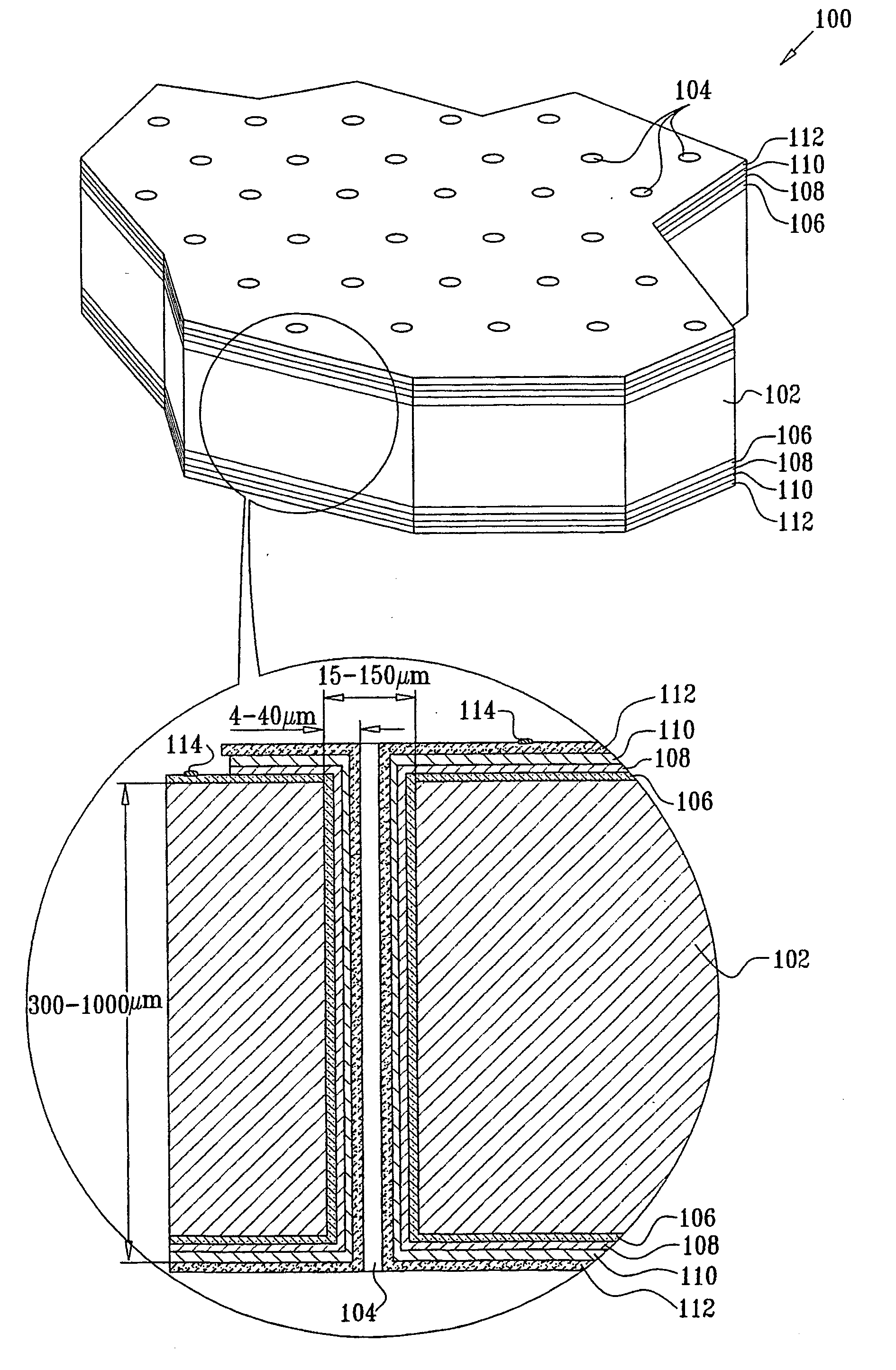
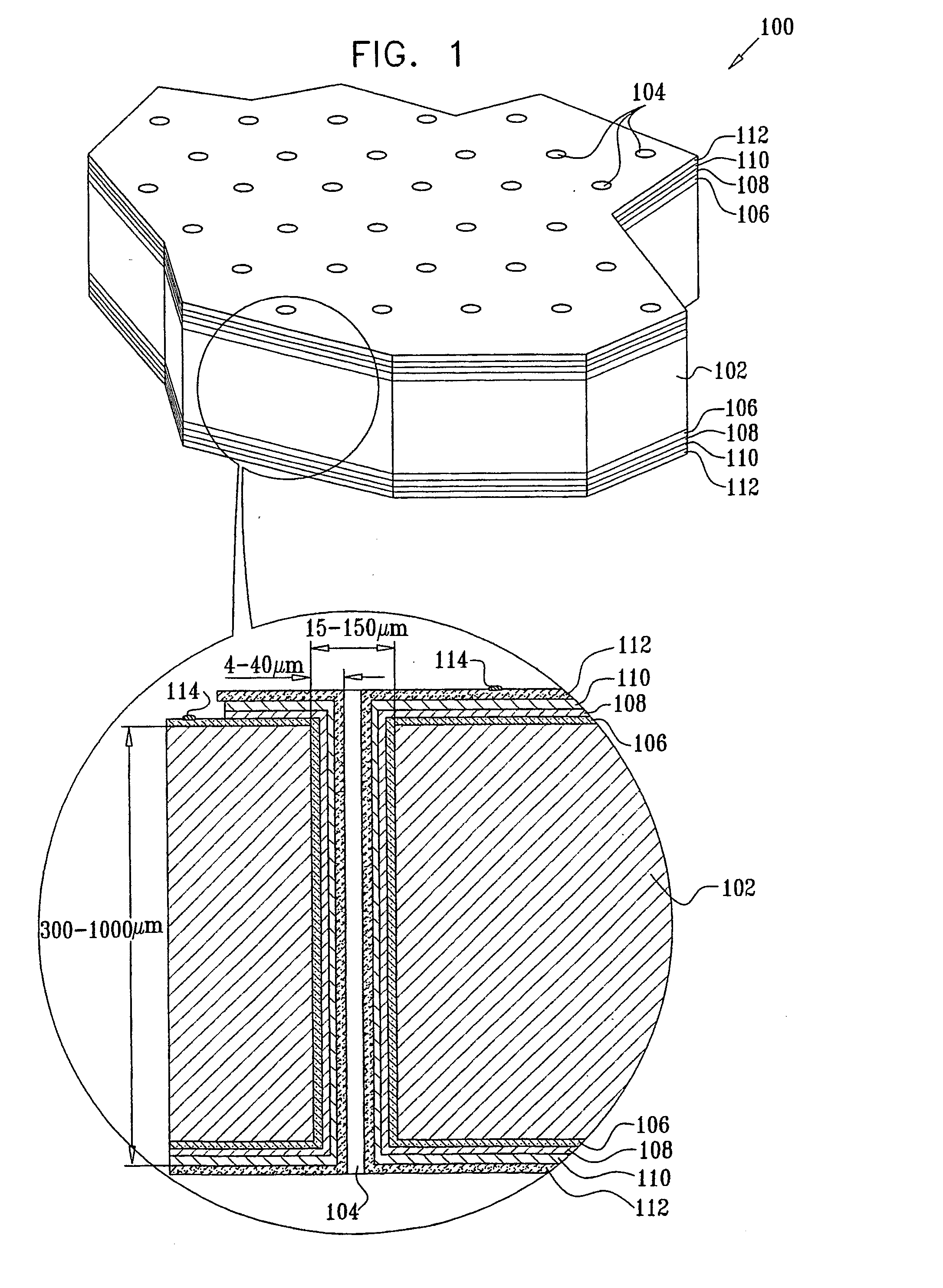
Thin-film cathode for 3-dimensional microbattery and method for preparing such cathode
a microbattery and thin film technology, applied in the field of thin film batteries, can solve the problems of low energy density, unsuitability for “conformity”, and limitations of existing planar technology
- Summary
- Abstract
- Description
- Claims
- Application Information
AI Technical Summary
Problems solved by technology
Method used
Image
Examples
example 1
[0084] A secondary electrochemical cell, consisting of a lithium anode, a hybrid polymer electrolyte and a MoS2 cathode on a silicon substrate, was assembled.
[0085] To remove organic and metallic residues, the silicon substrate was immersed in a solution of H2O2:NH4OH for 5 min at 70° C. and washed in deionized water with successive immersion into a H2O2:HCl mixture for another 5 min. After rinsing in deionized water, the substrate was etched in a NH4F:HF solution for 2 min. The surface activation was accomplished in a PdCl2:HCl:HF:CH3COOH solution at room temperature for 2 min.
[0086] A 0.3 μm thick cathode was prepared by reduction of MoS42− ions on a nickel coated silicon substrate at a constant current density of 10-15 mA / cm2. The nickel deposition was carried out in a NiSO4:NaH2PO2:EDTA (or CH3COONa) solution with pH of 4 and at an elevated temperature of 90° C. for a few minutes. The thickness of the nickel deposited is a function of time and can be varied.
[0087] The deposit...
example 2
[0091] A Li / composite polymer electrolyte (CPE) / MoS2 battery was assembled. The cathode was prepared as in Example 1.
[0092] A 50 μm thick film composite polymer electrolyte with a composition of LiImide1 P(EO)20 EC1 9% v / v Al2O3 was prepared from 45 mg LiImide, 300 mg P(EO), 30 mg EC and 100 mg Al2O3.
[0093] Poly(ethylene oxide) (P(EO)) was purchased from Aldrich, (average molecular weight 5×10⁶) and was vacuum dried at a temperature of 45 to 50° C. for about 24 hours. A polymer slurry was prepared by dispersing known quantities of P(EO), LiImide, and ethylene carbonate (EC) in analytical grade acetonitrile, together with the required amount of an inorganic filler, such as Al2O3 (Buehler) with an average diameter of about 150 A. To ensure the formation of a homogeneous suspension, an ultrasonic bath or high-speed homogenizer was used. The suspension was stirred for about 24 hours before the PE films were cast on the fine polished Teflon support (64 cm2 area). The solvent was allowe...
example 3
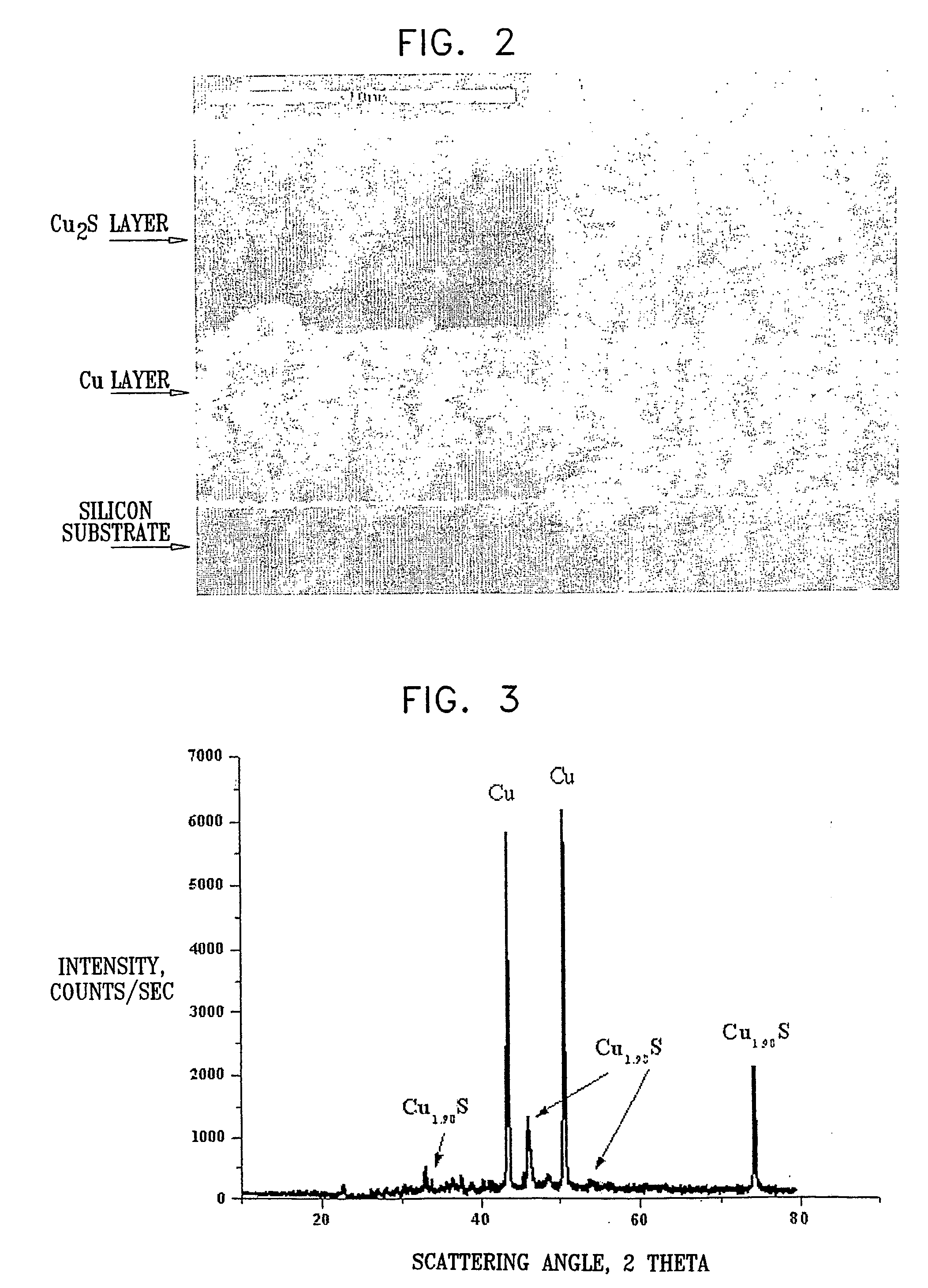
[0095] A Li / CPE / Cu2S cell with a 1 μm thick film composite cathode was prepared and assembled as described in Example 1, using the following materials: 33 mg LiI, 216 mg P(EO), 41 mg EC, 100 mg Al2O3. A 100% dense Cu2S cathode was prepared by anodic oxidation of a metallic copper layer electrodeposited on the electroless copper. The silicon substrate was pretreated, in solutions of H2O(5):H2O2(1):NH4OH(1), H2O(6):H2O2(1):HCl(1) at temperatures of 80-100° C. and in isopropanol, to remove oxides and organic contaminations. The sample was further wet-etched in a strong basic solution, then rinsed in water and immediately immersed in a Pd-containing solution to increase the catalytic activity of the silicon substrate surface. The solution for electroless copper deposition consisted of (g / L): 10-15 CuSO4x5H2O, 10-15 NaOH, 2-3 NiCl2xH2O, 0.001 Na2S2O8, 15-25 mL / L HCOH (37%).
[0096] The electrolyte for copper electrodeposition contained (g / L): 200-250 CuSO4x5H2O and 50-60 H2SO4. The electr...
PUM
| Property | Measurement | Unit |
|---|---|---|
| Electrical conductor | aaaaa | aaaaa |
| Semiconductor properties | aaaaa | aaaaa |
| Aspect ratio | aaaaa | aaaaa |
Abstract
Description
Claims
Application Information
 - R&D
- Intellectual Property
- Life Sciences
- Materials
- Tech Scout
- Unparalleled Data Quality
- Higher Quality Content
- 60% Fewer Hallucinations
Browse by: Latest US Patents, China's latest patents, Technical Efficacy Thesaurus, Application Domain, Technology Topic, Popular Technical Reports.
© 2025 PatSnap. All rights reserved.Legal|Privacy policy|Modern Slavery Act Transparency Statement|Sitemap|About US| Contact US: help@patsnap.com


