

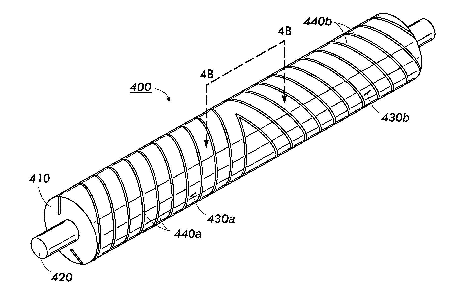
Imaging member belt support module
a flexible, electrostatographic technology, applied in the direction of optics, electrographic process apparatus, instruments, etc., can solve the problems of adversely affecting the toner transferring efficiency, fatigue-induced wrinkles or ripples in the belt, and substantial internal tensile strain (or stress) build-up in the charge transport layer, etc., to achieve enhanced electrostatographic imaging member belt cyclic imaging, robust dynamic mechanical cycling life function, and extensive image cycling life enhancement
- Summary
- Abstract
- Description
- Claims
- Application Information
AI Technical Summary
Benefits of technology
Problems solved by technology
Method used
Image

Examples
example i
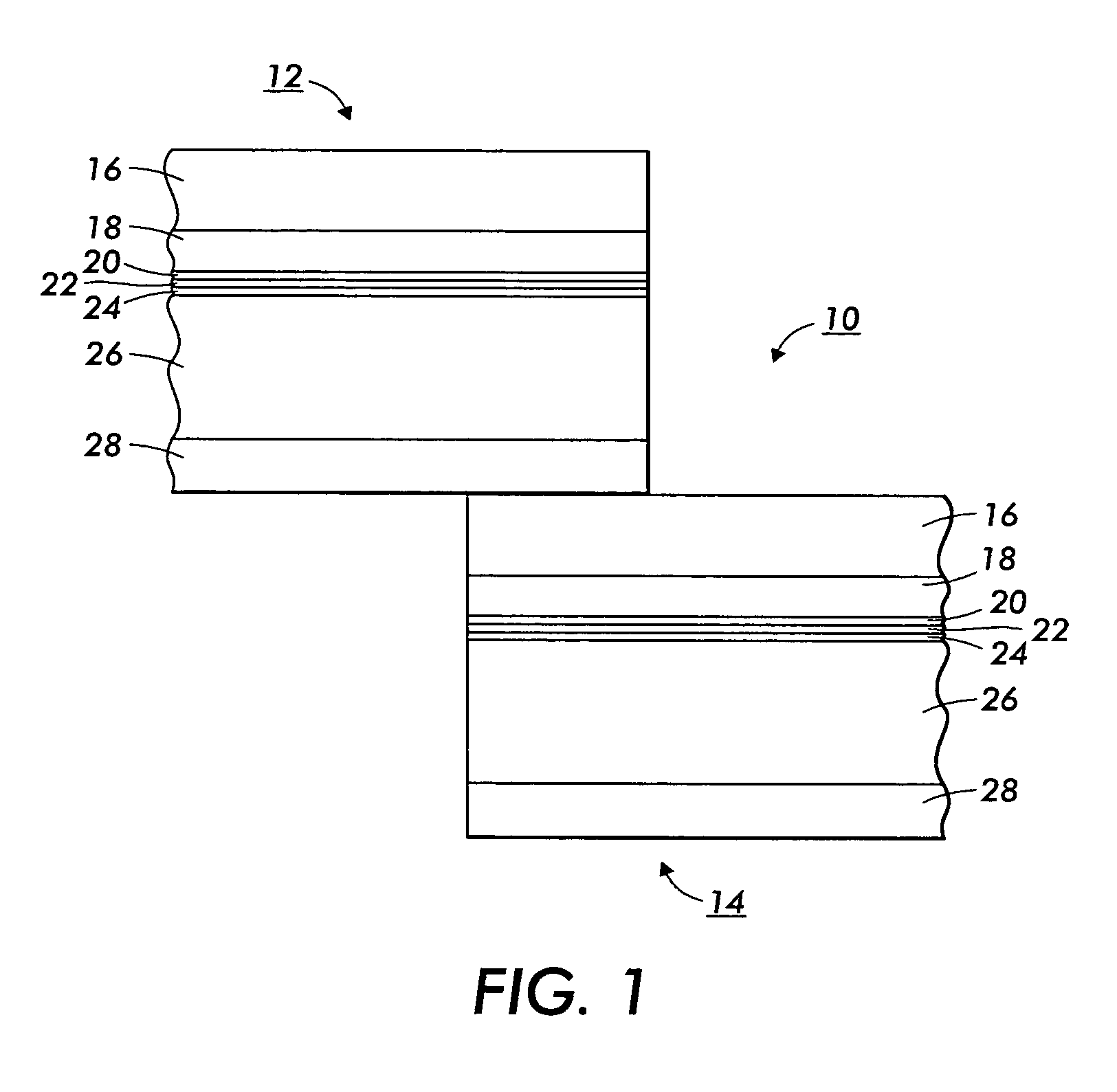
[0090] A flexible electrophotographic imaging member web stock, in reference to the illustration in FIG. 1, is prepared by providing a 0.01 μm thick titanium layer 24 coated onto a flexible biaxially oriented Polynaphthalate substrate support layer 26 (Kadalex®, available from ICI Americas, Inc.) having a thermal contraction coefficient of about 1.8×10⁻⁵ / ° C., a glass transition temperature Tg of 130° C., and a thickness of 3.5 mils or 88.7 μm, and applying thereto, by a gravure coating process, a solution containing 10 grams gamma aminopropyltriethoxy silane, 10.1 grams distilled water, 3 grams acetic acid, 684.8 grams of 200 proof denatured alcohol and 200 grams heptane. This layer is then dried at 125° C. in a forced air oven. The resulting blocking layer 22 has an average dry thickness of 0.05 μm measured with an ellipsometer.
[0091] An adhesive interface layer is extrusion coated by applying to the blocking layer a wet coating containing 5 percent by weight based on the total w...
example ii
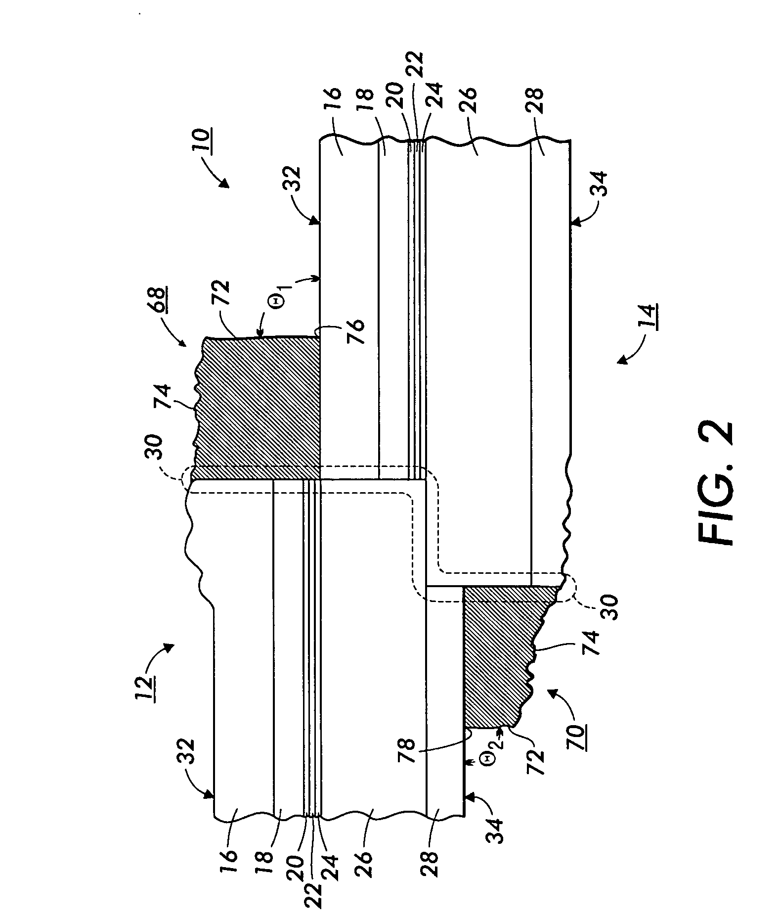
[0096] The prepared electrophotographic imaging member web stock of Example I is cut to provide two rectangular sheets, each having the dimensions of 2,808 mm in length and 440 mm in width, for ultrasonic seam welding them into two seamed imaging member belts. Seam welding process is carried out by first overlapping the 2 opposite ends of each rectangular imaging member sheet, to a distance of about one millimeter of one end over the other end, in a manner as that illustrated in FIG. 1, and then joining the overlapped region through application of conventional ultrasonic welding techniques, using 40 KHz sonic energy supplied to a welding horn, to form a seamed imaging member belt similar to the illustration of FIG. 2.
[0097] When cyclic tested in a belt support module, employing an active steering / tension roll for belt walk control, as that shown in FIG. 3, the first seamed imaging member belt is noted to develop early onset of ripples formations (see FIG. 7(a)) after only approxima...
PUM
 Abstract
Description
Claims
Application Information