Bipolar zero-gap type electrolytic cell

Active Publication Date: 2006-03-02
ASAHI KASEI KK
View PDF22 Cites 28 Cited by
  • Summary
  • Abstract
  • Description
  • Claims
  • Application Information

AI Technical Summary

Benefits of technology

[0026] The gas-liquid separation chambers are installed by extracting generated gas from the tops

Problems solved by technology

In these electrolytic cells, however, the mat strength, anode shape, electrolyte concentration distribution or in-cell pressure variations are not appropriate, which in turn gives rise to problems of an undesirable increase in voltage and breakage of the ion exchange membrane.
However, at a high current density of more than 5 kA/m2, the improvements are not enough for electrolysis with a stable long-term current efficiency and voltage.
However, the spring increases pressure in local areas and may cause damages to a membrane in contact with it.
This causes vibrations in the unit electrolytic cells and gives rise to a problem of possible breakage of the ion exchange membrane.
Further, they have no provisions inside for mixing electrolyte and have a problem that a large volume of electrolyte has to be circulated to evenly distribute the electrolyte within the electrolytic chamber.
However

Method used


Image

  • Bipolar zero-gap type electrolytic cell
  • Bipolar zero-gap type electrolytic cell
  • Bipolar zero-gap type electrolytic cell

Examples


application example 1

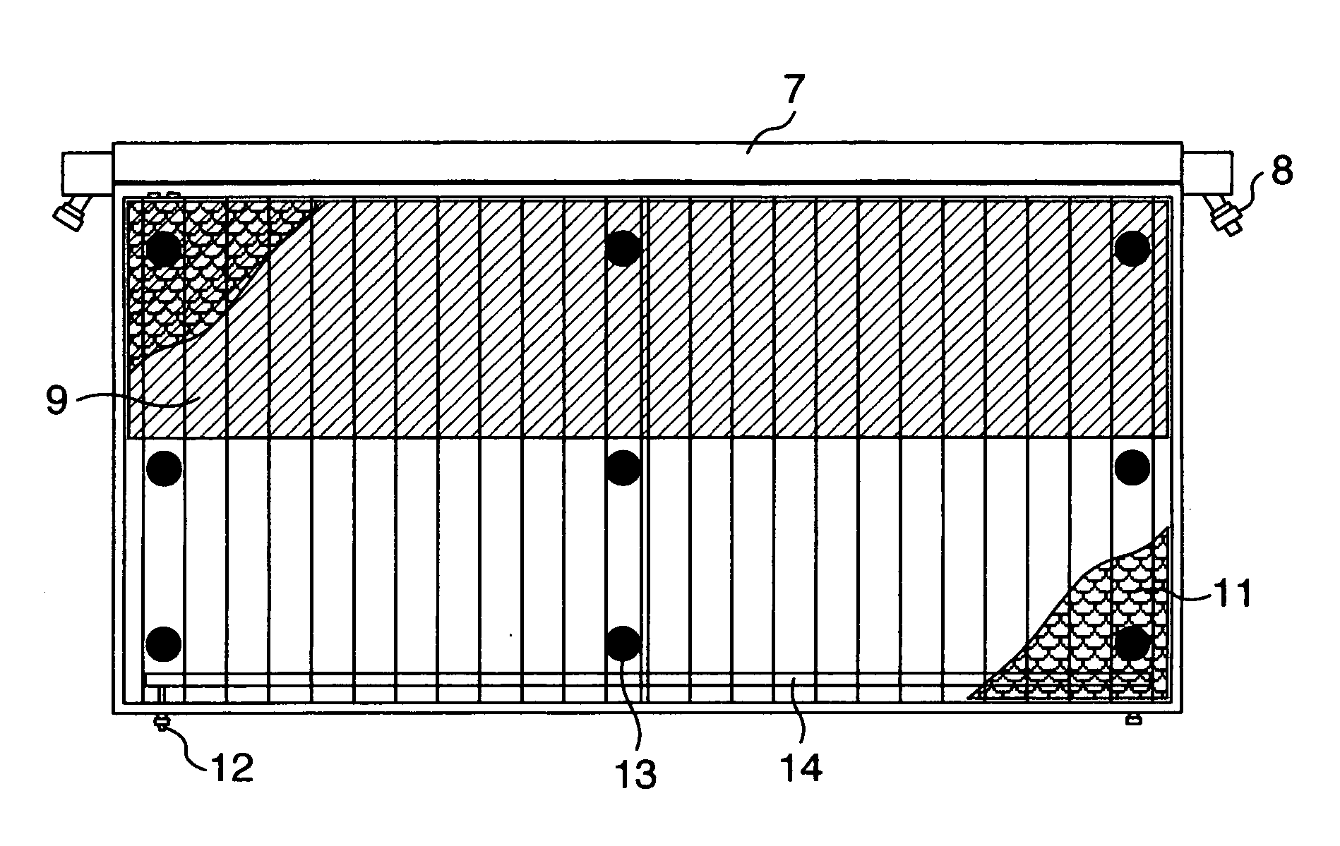
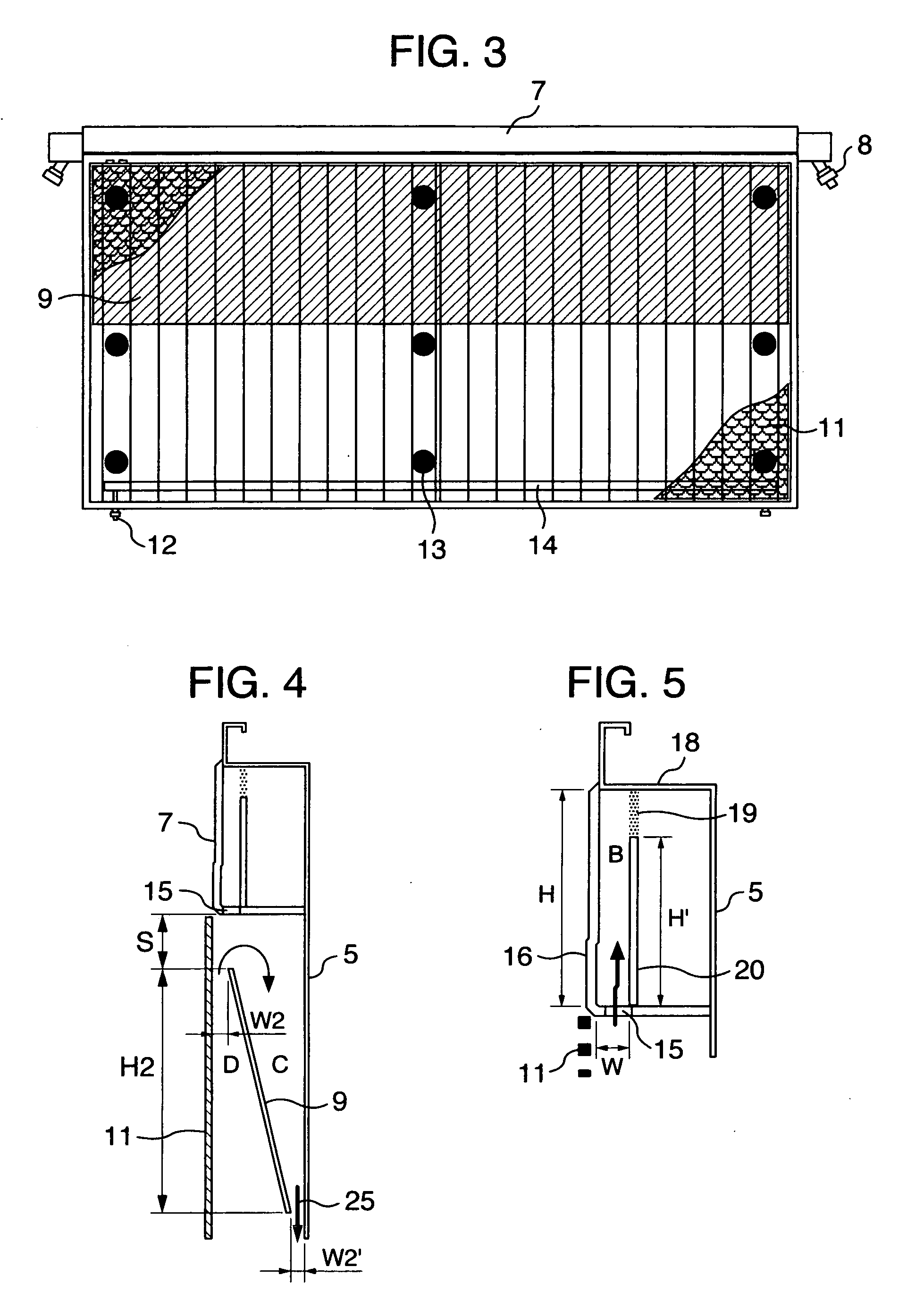
[0087] The bipolar, zero-gap type electrolytic cells 30 according to an embodiment of the invention, each of which has an anode structure and a cathode structure similar to those of FIG. 3 and FIG. 8 and a cross-sectional structure similar to that shown in FIG. 6, are arranged in series and assembled into an electrolyzer as shown in FIG. 7. FIG. 7 shows an anode unit cell disposed at one end of the assembly and a cathode unit cell disposed at the other end and with current lead plates 28 attached as shown.

[0088] The bipolar, zero-gap type electrolytic cell 30 measures 2400 mm wide by 1280 mm high and has an anode chamber, a cathode chamber and a gas-liquid separation chamber 7. The anode chamber and the cathode chamber are each formed by a flat pan-shaped separation wall 5 and are arranged back to back. These anode chamber and cathode chamber are combined together by inserting a frame member 22 into a bent portion 18 provided at the top of the separation wall 5. Each gas-liquid sep...

reference example 1

[0106] An electrolyzer was built by using similar bipolar electrolytic cells except that the hydrogen generating cathodes used in application example 1 were modified. Used as the hydrogen generating cathode was a 14 mesh nickel wire net of a 0.4 mm wire diameter (a cathode thickness of 0.8 mm) coated with a material composed mainly of nickel oxide to a thickness of about 250 μm.

[0107] After the electrolyzer was operated under exactly the same conditions as the application example 1, similar measurements were made. The results are shown in Table 2. The results show that voltage was relatively high from the initial stage, that its rise was as large as 80 mV for 6 kA / m2 and that the current efficiency degradation was as great as 2-3%. Vibrations in the electrolytic cell were less than 5 cm in the water column for 6 kA / m2 and a concentration difference was 0.31-0.35 N on the anode side and 0.6-0.8% on the cathode side.

[0108] After 360 days of the operation, the electrolyzer was disass...

application example 2

[0109] An electrolyzer was built by using similar bipolar electrolytic cells except that the anodes used in application example 1 were modified.

[0110] A titanium plate of 1 mm thickness was used as the anode and the titanium plate was expanded and roll-pressed to a thickness of 1.2 mm. An opening percentage was measured to be 40%. The expanded titanium plate was etched with sulfuric acid to form irregularities on its surface whose maximum height difference was about 30 μm. It was then coated with a material composed mainly of RuO2, IrO2 and TiO2. The maximum height difference between the irregularities on the coated surface was 13 μm. The electrolyzer was operated under exactly the same conditions as application example 1 and a similar measurement was made. Measured values are shown in Table 3. Table 3 shows that a voltage rise was 50 mV for 6 kA / m2 and current efficiency degradation was 1.3%. Vibrations in the electrolytic cell were less than 5 cm in the water column for 6 kA / m2 a...


PUM

PropertyMeasurementUnit
Lengthaaaaaaaaaa
Lengthaaaaaaaaaa
Fractionaaaaaaaaaa

Abstract

A bipolar zero-gap electrolytic cell comprising an anode comprising an anode substrate constituted of a titanium expanded metal or titanium metal net of 25 to 70% opening ratio, which anode after coating the substrate with a catalyst has a surface of 5 to 50 μm unevenness difference maximum and has a thickness of 0.7 to 2.0 mm. In this electrolytic cell, the possibility of breakage of ion exchange membrane is low, and the anolyte and catholyte have a concentration distribution falling within given range. With this electrolytic cell, stable electrolysis can be performed for a prolonged period of time with less variation of cell internal pressure.

Description

TECHNICAL FIELD [0001] The present invention relates to a bipolar, zero-gap type electrolytic cell. [0002] This is a bipolar electrolytic cell for use in a filter press type electrolyzer. The electrolyzer has many bipolar electrolytic cells arranged though the intermediary of cationic exchange membranes, each of which comprises an anode chamber and a cathode chamber arranged back to back. In the cathode chamber, there are at least two layers of a conductive cushion mat layer and a hydrogen generating cathode stacked over the cushion mat layer in an area where it contacts the cationic exchange membrane. [0003] This electrolytic cell has an anode having a base material formed of a titanium expanded metal or titanium wire mesh with an open-area percentage of 25% to 70%. The surface of the anode, after the base material has been applied with a catalyst, has a maximum height difference of 5 μm to 50 μm between ridges and troughs. The anode is 0.7 mm to 2.0 mm thick. BACKGROUND ART [0004]...

Claims


Application Information

Patent Timeline
IPC IPC(8): C25C7/00C25B9/00C25B9/20C25B11/03
CPCC25B11/03C25B9/206C25B9/77C25B11/052C25B9/19C25B1/46
Inventor HOUDA, HIROYOSHINOAKI, YASUHIDE
Owner ASAHI KASEI KK
Why Eureka
Try Eureka