
Optical driver including a multiphase clock generator having a delay locked loop (DLL), optimized for gigahertz frequencies

a multi-phase clock and driver technology, applied in the direction of generating/distributing signals, instruments, horology, etc., can solve the problems of difficult to meet the need for high-speed delay-locked loops (dlls), difficult to increase the frequency of voltage-controlled delays, and inconvenient conventional delay-locked loop circuits, etc., to achieve small delay time, easy manufacturing, and power consumption

Inactive Publication Date: 2006-03-02
SAMSUNG ELECTRONICS CO LTD
View PDF12 Cites 20 Cited by
  • Summary
  • Abstract
  • Description
  • Claims
  • Application Information

AI Technical Summary

Benefits of technology

The present invention provides a multiphase clock generator based on a delay locked loop (DLL) and comprised of delay cells, each with a delay time of N×"a target delay time (Δ)." The delay cells have small delay time and low power consumption. The multiphase clock generator can operate at a high frequency range and has a high resolution pulse-write strategy. The optical driving system includes the multiphase clock generator and a method for preventing "overlapping" of marks on adjacent grooves on an optical disc. The invention also provides an optical driving system with a low power consumption and high frequency range. The multiphase clock generator includes two delay chains and a filter to output a control voltage based upon detecting a phase difference between the input clock and a DLL output clock. The "technical effects" of the invention include improved manufacturing efficiency, reduced power consumption, and improved data storage capacity of optical discs.

Problems solved by technology

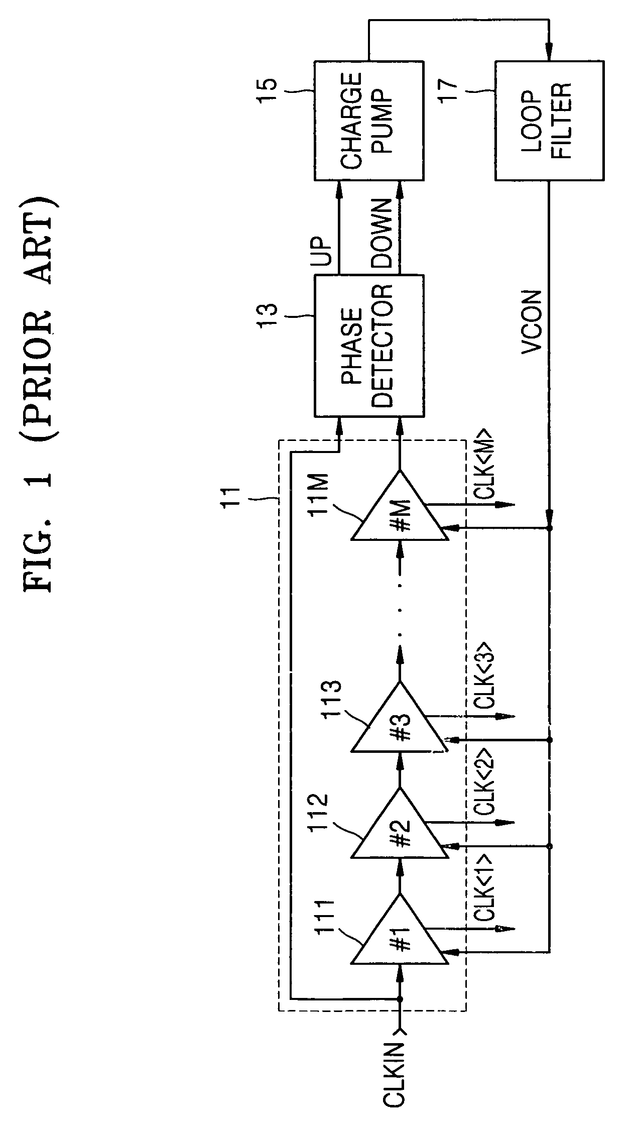
With increasing demand for higher optical disc burning (and reading) speeds, it has been difficult to meet the need for high-speed delay-locked loops (DLLs).
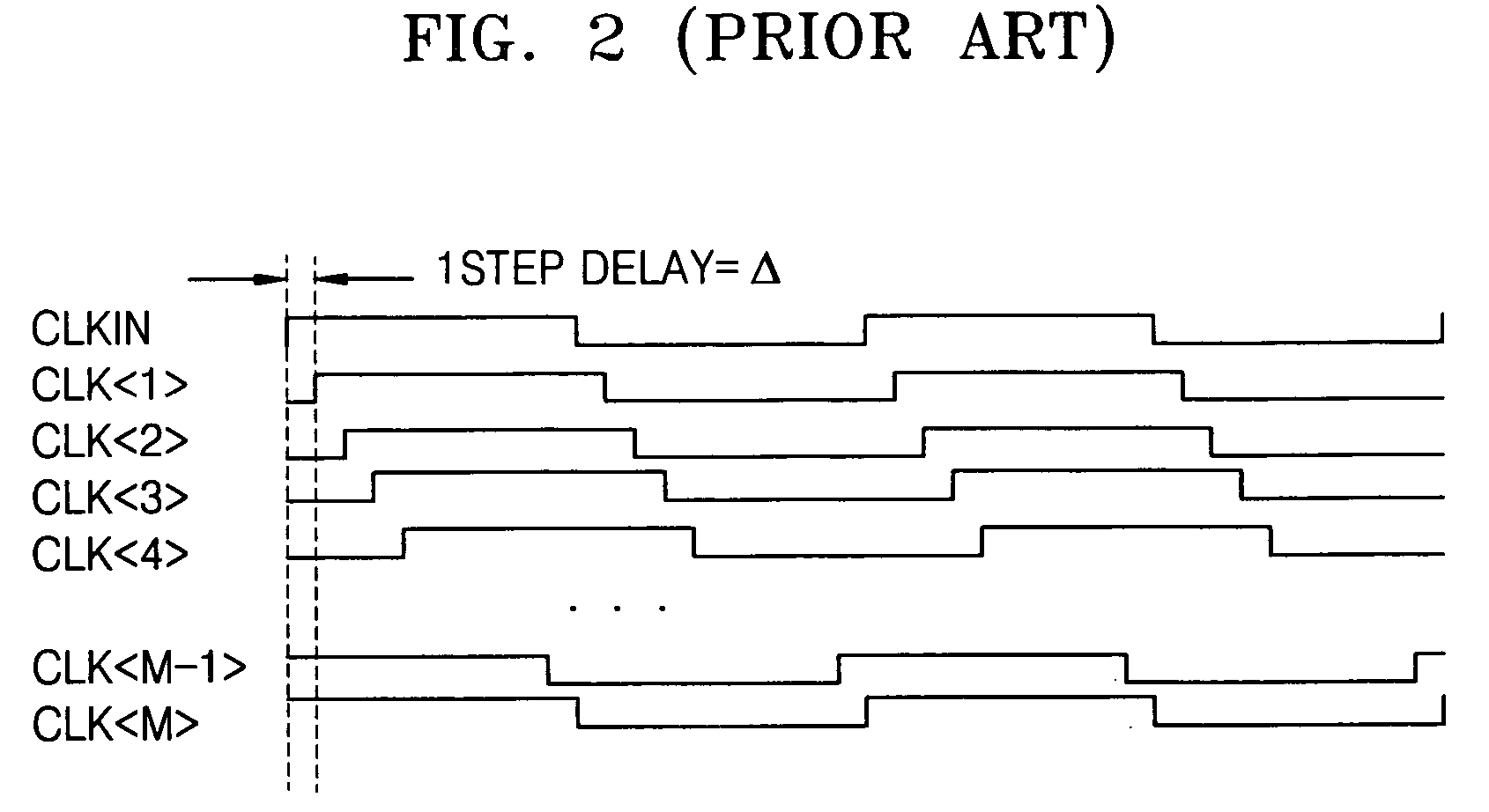
For example, it is not easy to increase the frequency of voltage-controlled delays (non-inverting buffers) included in a DLL to a high frequency approaching or above a GHz level (because propagation delay of such delay cells produced is constrained by the manufacturing process).
Therefore, the conventional delay locked loop circuit is inappropriate for an optical driving system requiring high frequency operation at 800 MHz or more (e.g., gigahertz frequencies).
It is difficult to make a delay cell having less than a 50 picosecond delay time because a propagation delay time is about 50 picoseconds with the general semiconductor manufacturing process.
The total power consumption in the DLL (delay locked loop) circuit is increased when “inner current” supplied to the delay cells is largely increased.
Therefore, the conventional DLL (delay locked loop) circuit is inappropriate for use as a multiphase clock generator in an optical driving system requiring high frequency operation at of 800 MHz or more.
Unfortunately, the resolution of a CD player's optics is not sufficient to read directly a sequence of 1s or 0s following each other too closely, i.e. 111111.
Another limitation is the maximum length of a given mark or space (pit or land), in order to leave room for the clock (synchronization) data.
Because of how the laser of a CD-player detects ones and zeroes on the CD, there cannot be consecutive ones when storing the digital information.
Accordingly, the mark written in one data groove can become overlapped with data in an adjacent data groove, causing a data read error because adjacent data grooves are overlapping.

Method used


Image

  • Optical driver including a multiphase clock generator having a delay locked loop (DLL), optimized for gigahertz frequencies
  • Optical driver including a multiphase clock generator having a delay locked loop (DLL), optimized for gigahertz frequencies
  • Optical driver including a multiphase clock generator having a delay locked loop (DLL), optimized for gigahertz frequencies

Examples


Embodiment Construction

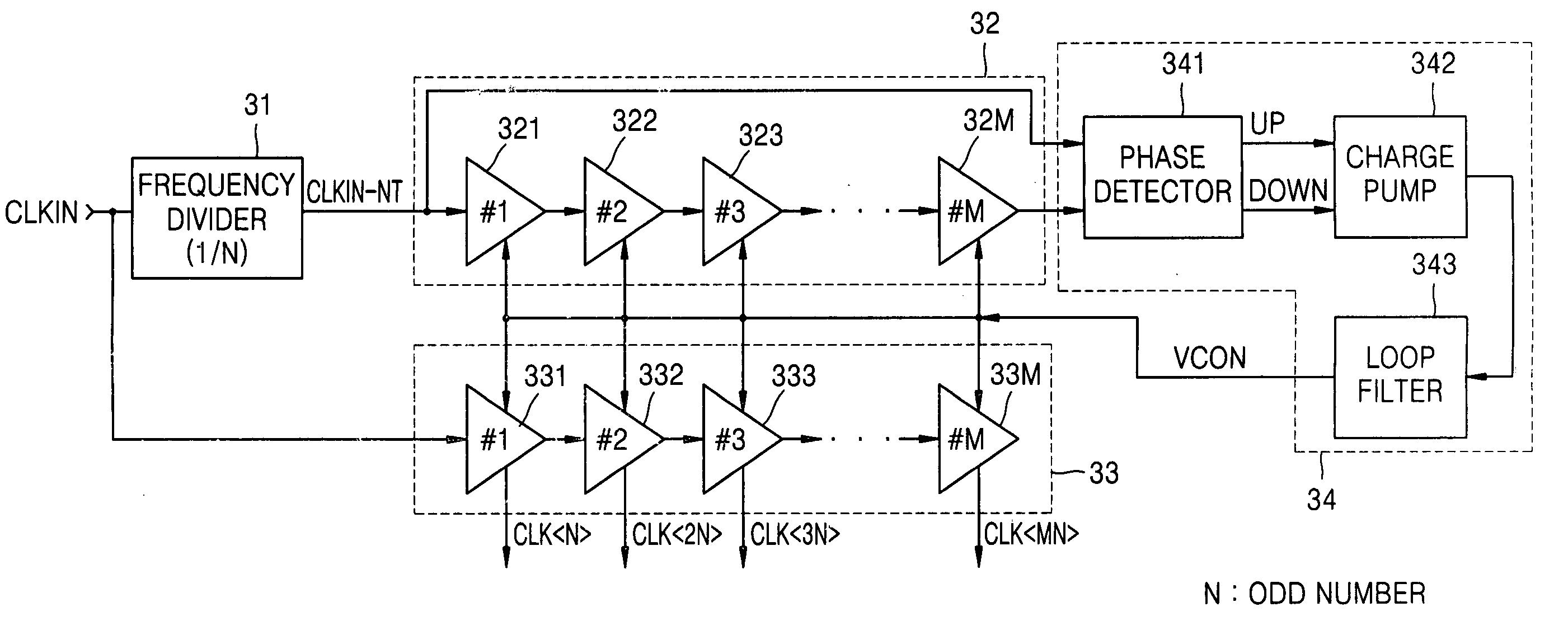
[0050]FIG. 3 is a circuit block diagram illustrating a DLL (delay locked loop) circuit according to an embodiment of the present invention. The DLL (delay locked loop) circuit of FIG. 3 will be explained in conjunction with FIGS. 4, and 5 which are a timing diagrams illustrating a number M of clock signals generated by the DLL circuit of FIG. 3. (e.g., when an input clock signal CLKIN frequency is 800 MHz, N=3 and M=32).

[0051] The multiphase clock generator based on a DLL (delay locked loop) circuit of FIG. 3 has a frequency divider (31), a first (main) delay chain (32), a second (replica) delay chain (33) and a control circuit (34) and a line transmitting a control voltage (VCON). The feedback loop formed by the first (main) delay chain (32), and the control circuit (34) and the control voltage (VCON), form a conventional DLL (delay locked loop) locked to the divided clock signal (CLKIN-NT, having a frequency f / N and period N×T) output by the frequency divider (31). The multiphase...


PUM

PropertyMeasurementUnit
frequencyaaaaaaaaaa
delay timeaaaaaaaaaa
propagation delay timeaaaaaaaaaa

Abstract

An optical (disc) driving system including the DLL based multiphase clock generator circuit capable of generating 32 different phases from input clock having a frequency of 800 MHz or greater. The multiphase clock generator includes on a delay locked loop (DLL) having a frequency divider for outputting an N-divided clock to a first set of M voltage-controlled delay cells within a feedback loop, and further including an identical set of M voltage-controlled delay cells outside of the feedback loop for delaying the undivided clock and for outputting M multiphase clocks. An optical driver circuit of an optical driving system and a method for implementing a write-strategy for preventing “overlapping” of marks written on adjacent grooves on an optical disc. The circuit and method produce multiple write-strategy waveforms (channels) switching at a high resolution (e.g., T / 32) in the Gigahertz frequency range.

Description

BACKGROUND OF THE INVENTION [0001] 1. Field of the Invention [0002] The present invention relates to an optical media disc driver circuit and in particular, an optical driver circuit having a multiphase clock generator including a delay locked loop (DLL) circuit. [0003] 2. Description of the Related Art [0004] DVD±R discs, which record data once, store data by using changes in the reflectivity of a photosensitive material on the disc. The system shines a tightly focused, relatively high-power, 650-nanometer (nm) red laser beam onto the surface of the DVD. The light causes a permanent change in the reflectivity of the disc's surface. Information can then be recovered by illuminating the disc's surface with a lower-powered laser light. A detector receives the reflected laser light, and the system uses the varying reflectivity to re-create the original data with great integrity. DVD±RW discs utilize temperature-induced phase changes in a very thin metal alloy layer deposited on the sur...

Claims


Application Information

Patent Timeline
Patent Type & Authority Applications(United States)
IPC IPC(8): H04L7/00G11B7/125
CPCG11B7/00456G11B7/0062G11B7/126H04L7/0337H03L7/0812H03L7/0891H03L7/0805H03L7/0816H02M3/07
Inventor KIM, HO-YOUNGKIM, YOUNG-SUB
Owner SAMSUNG ELECTRONICS CO LTD
Learn More