Digital stereotaxic manipulator with interfaces for use with computerized brain atlases

a digital stereotaxic and brain atlase technology, applied in the field of electromechanical devices, can solve the problems of difficult to achieve, difficult to achieve, difficult to obtain accurate and reliable results, etc., and achieve the effect of reducing the possibility of damage to the brain of the animal and good resolution

Inactive Publication Date: 2006-03-09
SCOUTEN CHARLES W +2
View PDF6 Cites 20 Cited by
  • Summary
  • Abstract
  • Description
  • Claims
  • Application Information

AI Technical Summary

Benefits of technology

[0067] Computerized hardware and software can allow stereotaxic procedures being performed on lab animals to interact, on a “live” or “real-time” basis, with information that has been compiled in stereotaxic brain atlases, which have been prepared for various species of lab animals used in neurology research. As one example, during an invasive procedure, a researcher can see, on a cross-sectional brain map displayed on a full-sized computer monitor, the location and travel of an instrument tip, indicated by means such as a bright blinking cursor or icon. If desired, important brain structures (such as major nerve bundles) can been prominently labeled and/or colored, to clearly indicate their locations, and help the researcher ensure that they are avoided. This type of interactive display of information, shown on a “live” or “real time” basis on a computer monitor, can help a researcher guide an instrument tip to an exact targeted location, via a predetermined route that will inflict the least possible damage on the animal's brain. The computer can be programmed to display continuous

Problems solved by technology

Obtaining accurate and reliable readings, for all three vernier scales on all three orthogonal axes, is tedious, time-consuming, and often awkward and difficult, especially in tests carried out in cluttered and crowded settings, or under a hood or other enclosure or equipment.
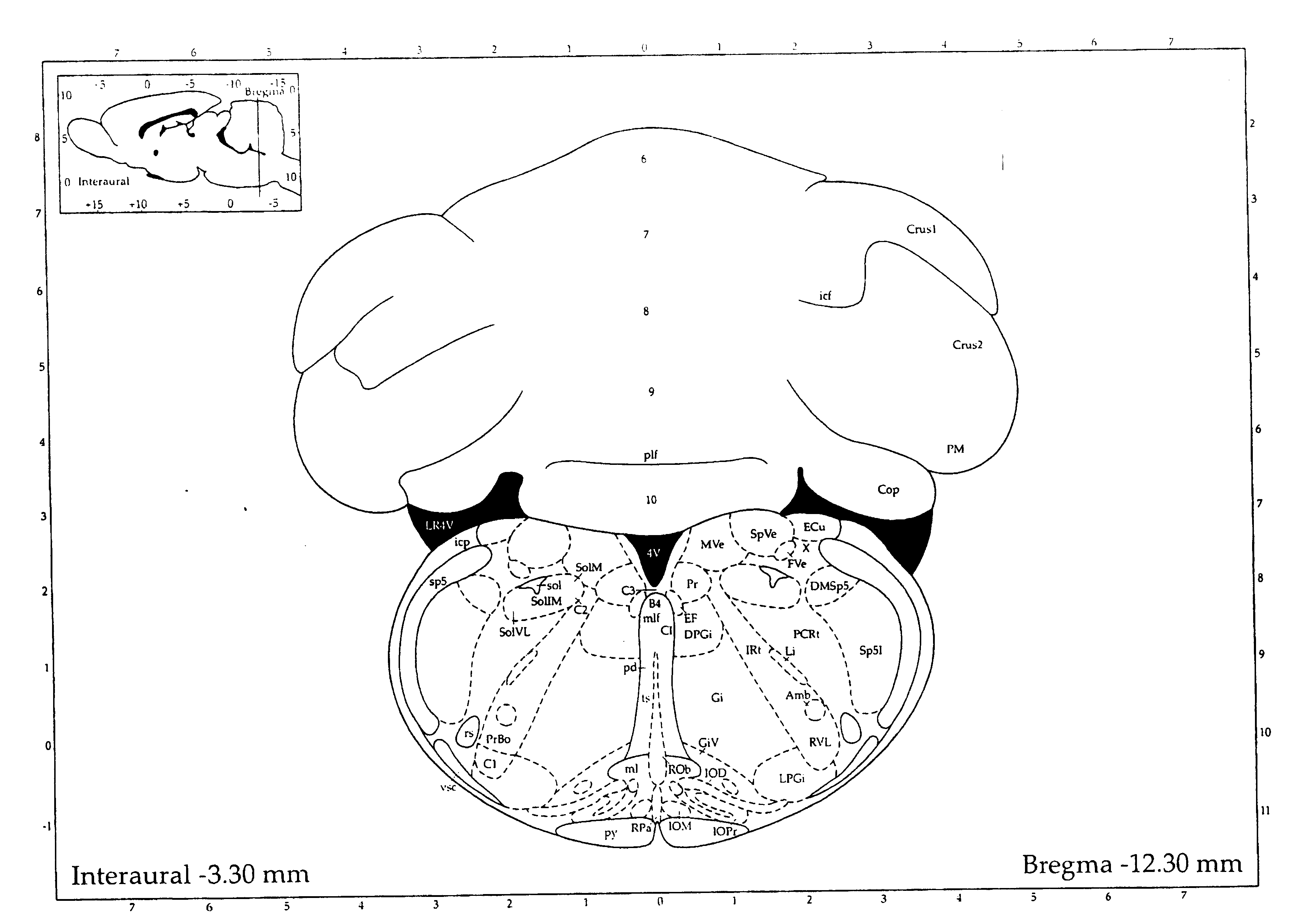
In addition, the types of calculations (mainly subtraction) that are required to determine positions relative to an arbitrary “zero spot” called the bregma (located at the intersection of two “fissures” or “sutures” that are visible on the top of an exposed rat skull) are tedious and prone to error, when vernier scales are used and numerous digits must be manually punched into some type of keypad.
Any reference herein to animals is limited to non-human animals, and stereotaxic manipulators as used herein are limited to systems used in research, rather than surgery in human medicine.
It should be recognized that extraordinarily complex, expensive, and sophisticated systems have been developed for certain types of surgery on humans, especially on human brains, spinal cords, and hearts.
However, those are vastly too expensive to justify their use in animal research, which faces entirely different economic and competitive limitations and boundaries.
In addition, complexity and training impose two other major constraints on how complex or sophisticated a stereotaxic manipulator can be, for use in research on small animals.
The training that is required, before a surgeon can use a complex computerized machine in human surgery, utterly dwarfs the training that can reasonably be expected, or provided, before a researcher begins trying tests on mice or rats.
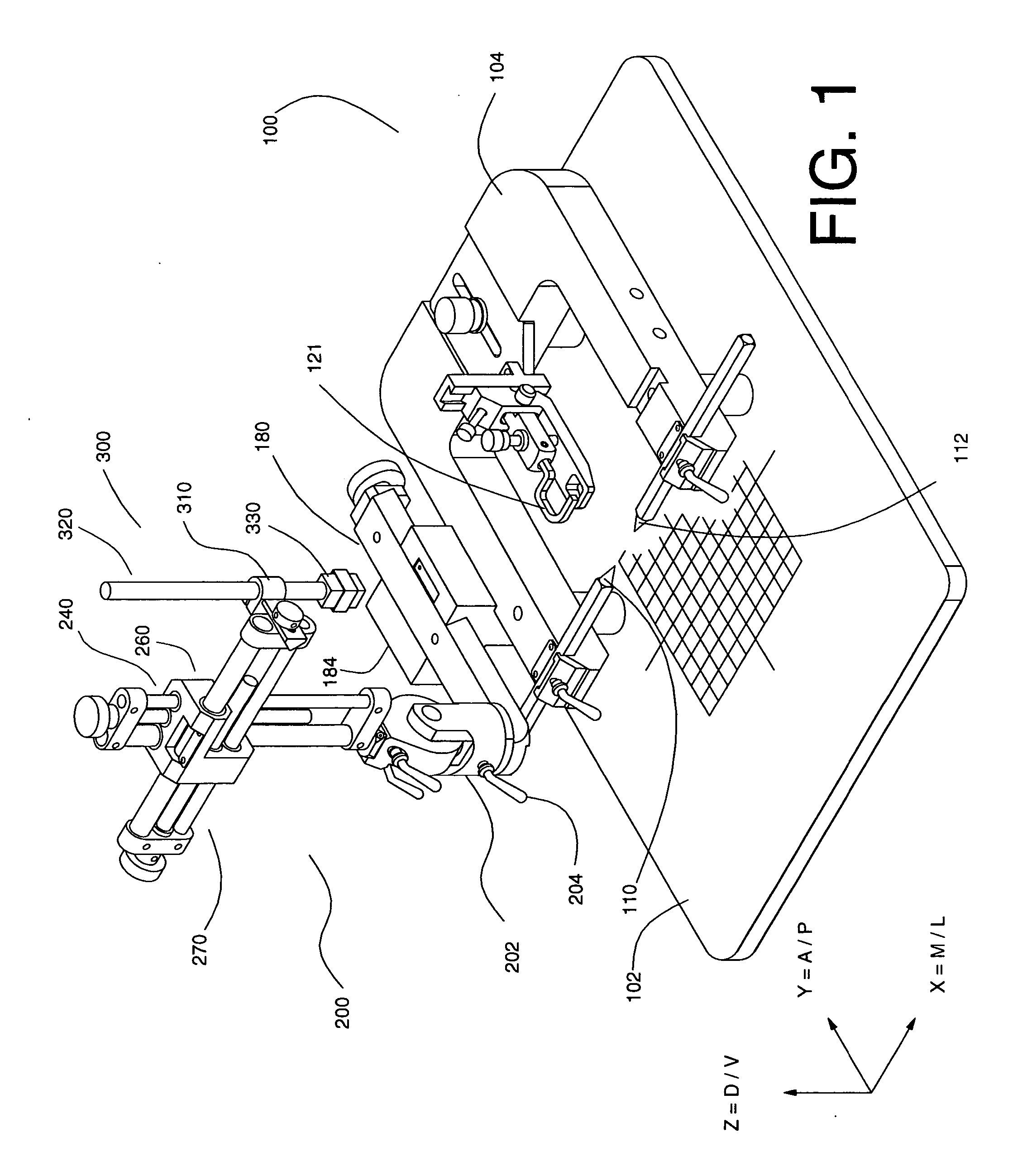
However, the earliest models suffered from several limitations.
They were relatively large and cumbersome, which are major disadvantages in most laboratory settings, which almost always involve crowded benchtops.
They also were relatively expensive, and a new complete system (including the baseplate, manipulator mount and slide, etc.) had to be purchased, with no means for retrofitting already-owned manipulators.
For those and other reasons, s

Method used


Image

  • Digital stereotaxic manipulator with interfaces for use with computerized brain atlases
  • Digital stereotaxic manipulator with interfaces for use with computerized brain atlases
  • Digital stereotaxic manipulator with interfaces for use with computerized brain atlases

Examples


Embodiment Construction

[0078] As summarized above, this invention discloses certain enhancements for a combination device that was previously described in utility patent application Ser. No. 10 / 636,899, filed in August 2003. That system has been publicly advertised and sold by Coretech Holdings and its subsidiary, myNeuroLab, since shortly after the filing of that application.

[0079] Briefly, a “baseline” system that does not include the enhancements of this current invention includes the following major subassemblies and components:

[0080] (1) a stereotaxic manipulator 3000 (with a general structure such as shown in FIGS. 1-3) for holding rats, mice, or other non-human animals, which has been equipped with both: (i) linear scales and electronic reader heads that enable digital measurement of linear motion of an instrument tip along all three orthogonal axes, such as scale-and-reader combinations 512 and 514 (on slide 180), 542 and 554 (in vertical arm 240), and 562 and 574 (on horizontal arm 270); and, (...


PUM


Abstract

A system is disclosed that allows stereotaxic procedures being performed on lab animals to interact, on a “live” or “real-time” basis, with information that has been compiled in stereotaxic brain atlases. For example, during an invasive procedure, a researcher can see, on a cross-sectional brain map displayed on a full-sized computer monitor, the location and travel of an instrument tip, indicated by means such as a bright blinking cursor or icon. If desired, important brain structures (such as major nerve bundles) can been prominently labeled and/or colored, to clearly indicate their locations, and help the researcher ensure that they are avoided. This system can be provided by coupling a digital stereotaxic manipulator to a dedicated controller with touch-screen capability, and coupling the PLC processor to a computer having a monitor screen that is large enough to display a brain map with good resolution. Alternately, the digital stereotaxic manipulator can be coupled directly to a computer, via an interface card or other device.

Description

FIELD OF THE INVENTION [0001] This invention relates to equipment used in biological and medical research that uses small animals, such as rats or mice. In particular, it relates to electromechanical devices, called stereotaxic holders, that can be coupled to computers. BACKGROUND OF THE INVENTION [0002] Background information on stereotaxic holders used in neurological research on rats, mice, and other small animals is provided in parent application Ser. No. 10 / 636,899, cited above, invented by the same inventors herein, and assigned to Coretech Holdings, which also owns all rights to this current application. The contents and teachings of that parent application are incorporated herein by reference, as though fully set forth herein. [0003] In order to establish component names and callout numbers used herein, FIG. 1 herein depicts a conventional prior art non-digital stereotaxic holder and manipulator, of the type that was used with essentially no changes for nearly 40 years, from...

Claims


Application Information

Patent Timeline
IPC IPC(8): A61B5/05
CPCA61B19/201A61B19/203A61B19/52G09B23/30A61B2017/00221A61B2019/5259A61B2019/566A61B19/5244A61B90/36A61B2034/256A61B34/20A61B90/11A61B90/14A61B2034/2059
Inventor SCOUTEN, CHARLES W.UNNERSTALL, JAMES G.THOMPSON, JOHN M.
Owner SCOUTEN CHARLES W
Why Eureka
Try Eureka