Prostheses for spine discs having fusion capability

Inactive Publication Date: 2006-03-09
UNIV OF SOUTH FLORIDA
View PDF21 Cites 77 Cited by
  • Summary
  • Abstract
  • Description
  • Claims
  • Application Information

AI Technical Summary

Benefits of technology

[0012] Two devices are contemplated with one on each lateral side for all disc replacements. For treating certain deformities, such as scoliosis, the two devices will contain unequal amounts of hydraulic element with one larger thereby counteracting the natural scoliotic curve. The hydraulic element can be added before, during or after surgery.
[0013] It is not uncommon for the biomechanical behavior of a disc replacement to degrade over time, or for the device not to perform as expected in any given patient. The current surgical strategy in these cases is to remove the disc and fuse the vertebra. Fusing the vertebra places additional stress on the adjacent discs, which can result in early failure, and limits patient flexibility.
[0014] A major benefit of the present invention is the ability to convert the device to a fusion element. No existing or contemplated disc prosthetic devices disclose a method for salvage, revision, or conversion to fusion. The device in accordance with the present invention may need to be converted to fusion mass if its biomechanical behavior degrades over time. Additionally, there are many reasons why one device or another does not perform as expected in any given patient. Many of the reasons are not understood. Current disc prostheses designs generally require physical removal and subsequent revision or replacement with a standard fusion procedure. Such procedures are costly in terms of morbidity and money. The present invention allows for percutaneous injection of bone forming materials into the device, allowing bone to form between the adjacent vertebral bodies forming a bony fusion. Removal of some or substantially all the

Problems solved by technology

Degenerative disc disease results in significant pain for a large population of patients.
Instrumentation, such as cages and screws and rods can migrate, causing serious neurological complications.
For those patients in whom fusion was successful, there appears to be a greater likelihood of adjacent disc failure.
While this has not been conclusively proven, it is clear that the adjacent levels are subject to higher stresses due to loss of range of motion at the fused disc.
Additionally, there is a loss of mobility at the fused level that varies with location in the spine.
Scoliosis is also a degenerative disease in that the spine curvature progresses and

Method used


Image

  • Prostheses for spine discs having fusion capability
  • Prostheses for spine discs having fusion capability
  • Prostheses for spine discs having fusion capability

Examples


Embodiment Construction

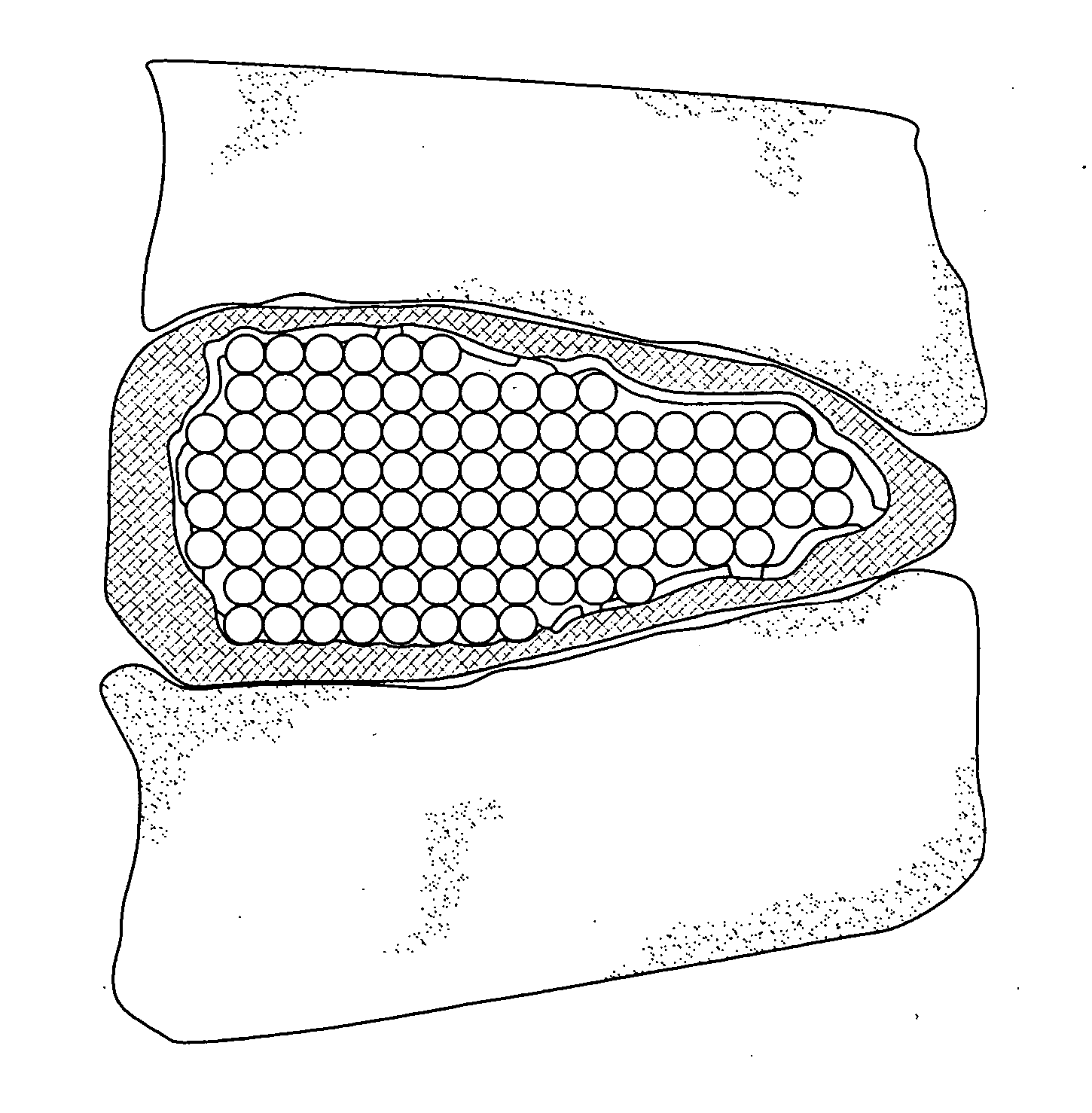
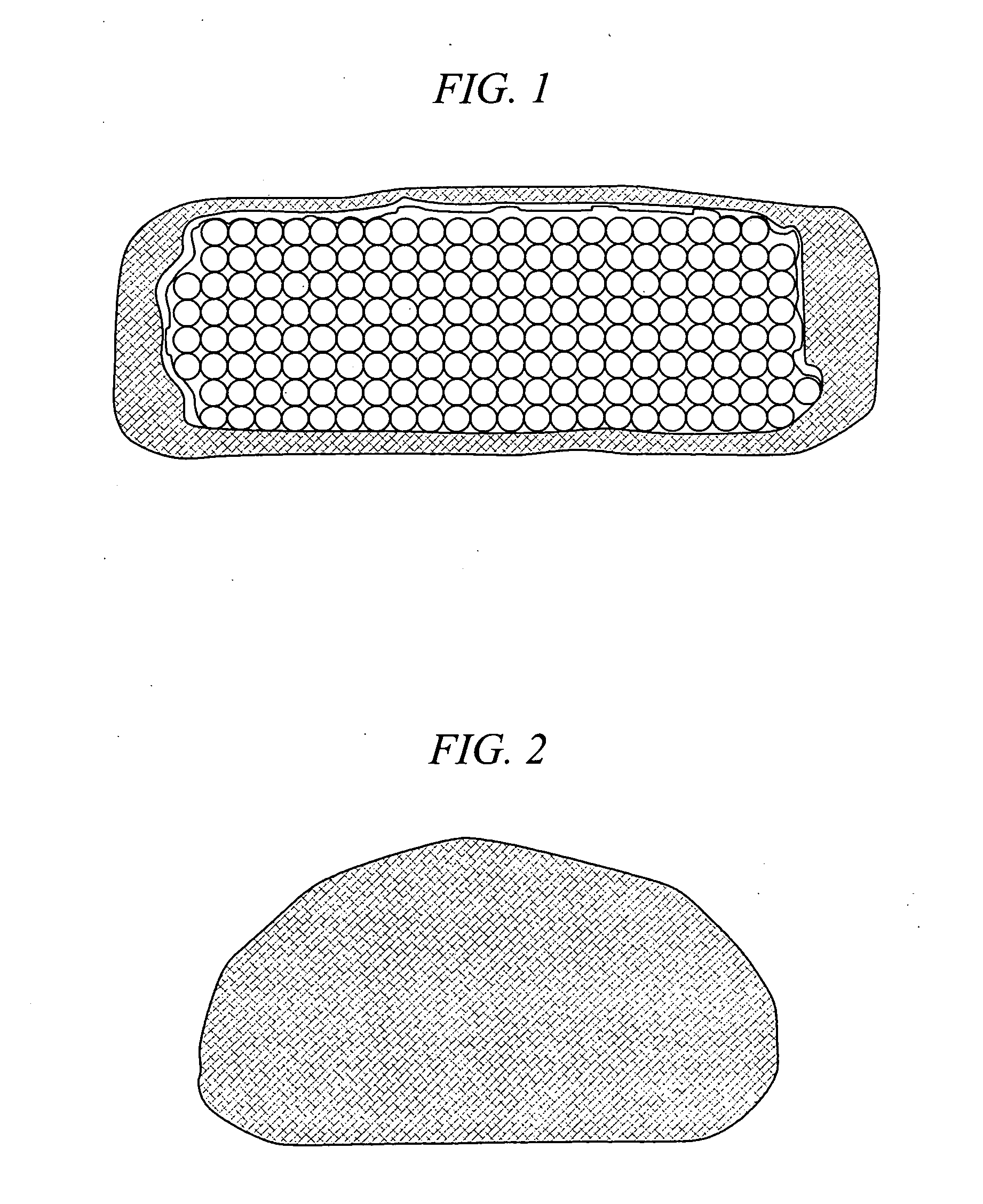
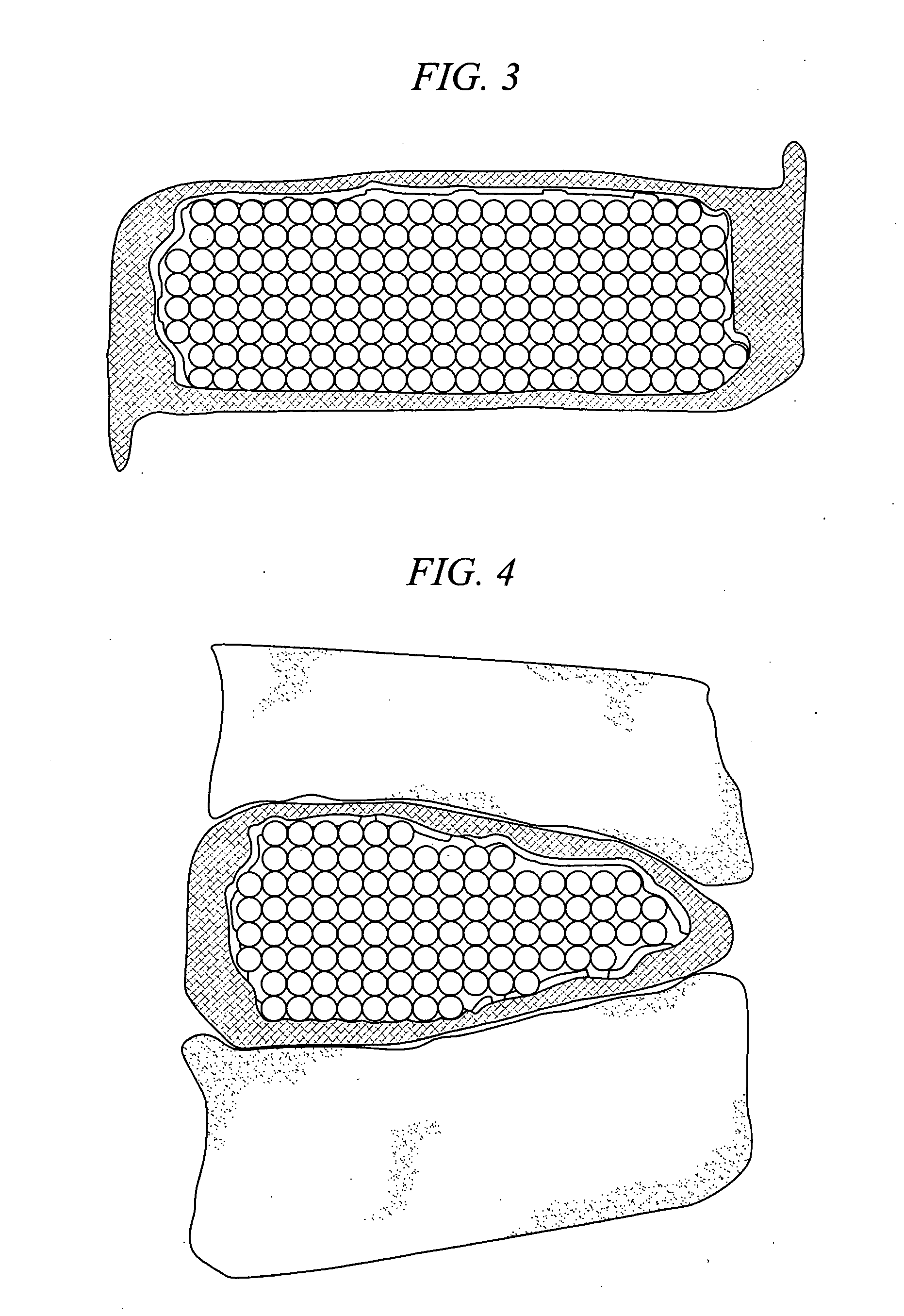
[0026] The present invention is a medical device and method. The device consists of two implantable parts the two parts of the device will be implanted in a disc space after discectomy. The surgical approach can be posterior or anterior, although posterolateral is preferred. The device will be of a size to be implanted in a minimally invasive or endoscopic manner. The device is dry prior to implantation and fits into a space approximately 9 mm by 12 mm long. After positioning in the disc space and possible use of initial fixation, the device is saturated with normal saline and the incision closed. Post operatively, the hydraulic element absorbs water and swells to several times their dry size. The hydraulic element may be added before, during or after the operation. Addition of hydraulic element to one of the two devices may be made to provide asymmetry for correction of spine deformities, such as scoliosis.

[0027] With reference to FIG. 1 and FIG. 2, in accordance with one embodime...


PUM

PropertyMeasurementUnit
Volumeaaaaaaaaaa
Timeaaaaaaaaaa
Stiffnessaaaaaaaaaa

Abstract

The present invention provides both a device and a method. The device is a human made replacement for the soft discs in the spine. A fabric pouch encloses a central hydraulic element made up of small soft beads. Two pouches with beads are implanted into a prepared disc space to function as an intervertebral disc. The method is conversion of the device into a fusion element.

Description

CROSS-REFERENCE TO RELATED APPLICATIONS [0001] This application claims priority to U.S. Provisional Patent Application No. 60 / 608,209, filed Sep. 9, 2004, the contents of which are herein incorporated by reference.BACKGROUND OF INVENTION [0002] Degenerative disc disease results in significant pain for a large population of patients. The current standard of care is an instrumented fusion using a variety of surgical approaches. In the procedure, the intervertebral disc is removed (discectomy) and replaced with a stiff strut or cage. Many times, additional plates, rods and screws are used to stabilize the construct as it heals. The healing process has the goal of vertebral body bony fusion across the disc space. In some cases, as many as 20%, fusion does not occur. Instrumentation, such as cages and screws and rods can migrate, causing serious neurological complications. In patients who smoke, fusion success is even smaller. For those patients in whom fusion was successful, there appea...

Claims


Application Information

Patent Timeline
IPC IPC(8): A61F2/44
CPCA61F2/441A61F2/442A61F2002/30009A61F2002/30075A61F2002/30242A61F2250/0028A61F2002/30914A61F2002/4495A61F2210/0061A61F2230/0071A61F2002/30586
Inventor JOHNSON, WESLEY M.FREEMAN, THOMAS B.
Owner UNIV OF SOUTH FLORIDA
Why Eureka
Try Eureka