Epitrochoidal crankshaft mechanism and method

a crankshaft and epitrochoidal technology, applied in the direction of cranks, gearing, machines/engines, etc., can solve the problems of inability to achieve advantages, force the lowering of the cr to a point where, and the attempt to enhance the internal combustion engine in this configuration has been limited, so as to achieve greater output, increase the work of the piston, and enhance the force and distance of the piston travel

Active Publication Date: 2006-03-16
MAROZZI
View PDF22 Cites 20 Cited by
  • Summary
  • Abstract
  • Description
  • Claims
  • Application Information

AI Technical Summary

Benefits of technology

[0048] Since an engine equipped with the Epitrochoidal crankshaft allows a greater volume of fuel mixture to be ingested for each power phase, the engine's output will be greater. The enhanced cylinder filling occurs at all engine speeds, so horsepower and torque curves obtained from dynamometer testing will indicate an improvement throughout the entire RPM range. As an example, the two-stroke cycle inventive prototype engine traps approximately 15 percent more fuel mixture on every compression phase. This increased volume is due to the lowering of the exhaust port and the added volume in the cylinder head to maintain the original trapped CR of the standard engine. Since the exhaust port opens first and closes last in this engine, both the force and distance of the piston travel are enhanced and therefore produce more work on the piston. Comparing the horsepower and torque curves of the engine equipped with the Epitrochoidal crankshaft to the curves generated by a standard engine will reveal that the inventive engine's curves are similar in shape to the standard engine's curves, but elevated at all points by 15 percent. At the peak point on the standard engine's horsepower curve, the Epitrochoidal crankshaft equipped engine will produce 15 percent more power. Horsepower curves are typically ‘bell’ shaped, with the peak horsepower value occurring at the top of the bell. If the greatest amount of horsepower that the standard engine could produce were all that were desired, the inventive engine, having a similar but elevated power curve, would be required to rotate at a lower RPM in order to achieve that power output. At lower engine speeds, fuel consumption is reduced while the original power levels are maintained.

Problems solved by technology

Attempts to enhance an internal combustion engine within this configuration have been limited to some extent by the physical and mechanical properties of the materials used to construct the engine, as well as the thermodynamic properties of the fuel and its delivery into the cylinder.
However, there are several reasons why these advantages cannot be realized.
Detonation of the fuel mixture during this dwell period is very likely and would force the lowering of the CR to a point where engine efficiency would suffer.
Time consumed at or near TDC results in less time being available to push the piston down the bore, scavenge the exhaust gases from the cylinder, and / or to refill the cylinder with the next fuel mixture.
Without sufficient time to separate and accomplish these individual events completely, the engine's efficiency will suffer due to the overlapping of the required events, and some mixing of exhaust residue with the fresh fuel mixture will result.
However, such is not the case in the referenced attempts.
In a similar manner, claims of increases in leverage or moment arm fail to mention that on a per-degree basis, the pressure above the piston's crown falls at a more rapid rate, destroying any potential torque gains.
The increased leverage causes the piston to move a greater distance for every degree of crankshaft rotation, which increases the trapped volume within the cylinder.
This lowers the pressure within the cylinder and results in a loss of force to act on the increased moment arm.
Therefore, any increases in engine output must be gained through increasing the work done on the piston, yet prior attempts that altered crankshaft motion were unable to achieve this result.
This in turn lowers the pressure within the combustion space considerably.
This means that a larger volume of fuel mixture can be trapped at the beginning of every compression phase.
If the actual CR were to be retained at a value identical to a standard engine, the volume of the combustion chamber must be increased as well, resulting in even greater trapped volume than would normally occur.

Method used


Image

  • Epitrochoidal crankshaft mechanism and method
  • Epitrochoidal crankshaft mechanism and method
  • Epitrochoidal crankshaft mechanism and method

Examples


Embodiment Construction

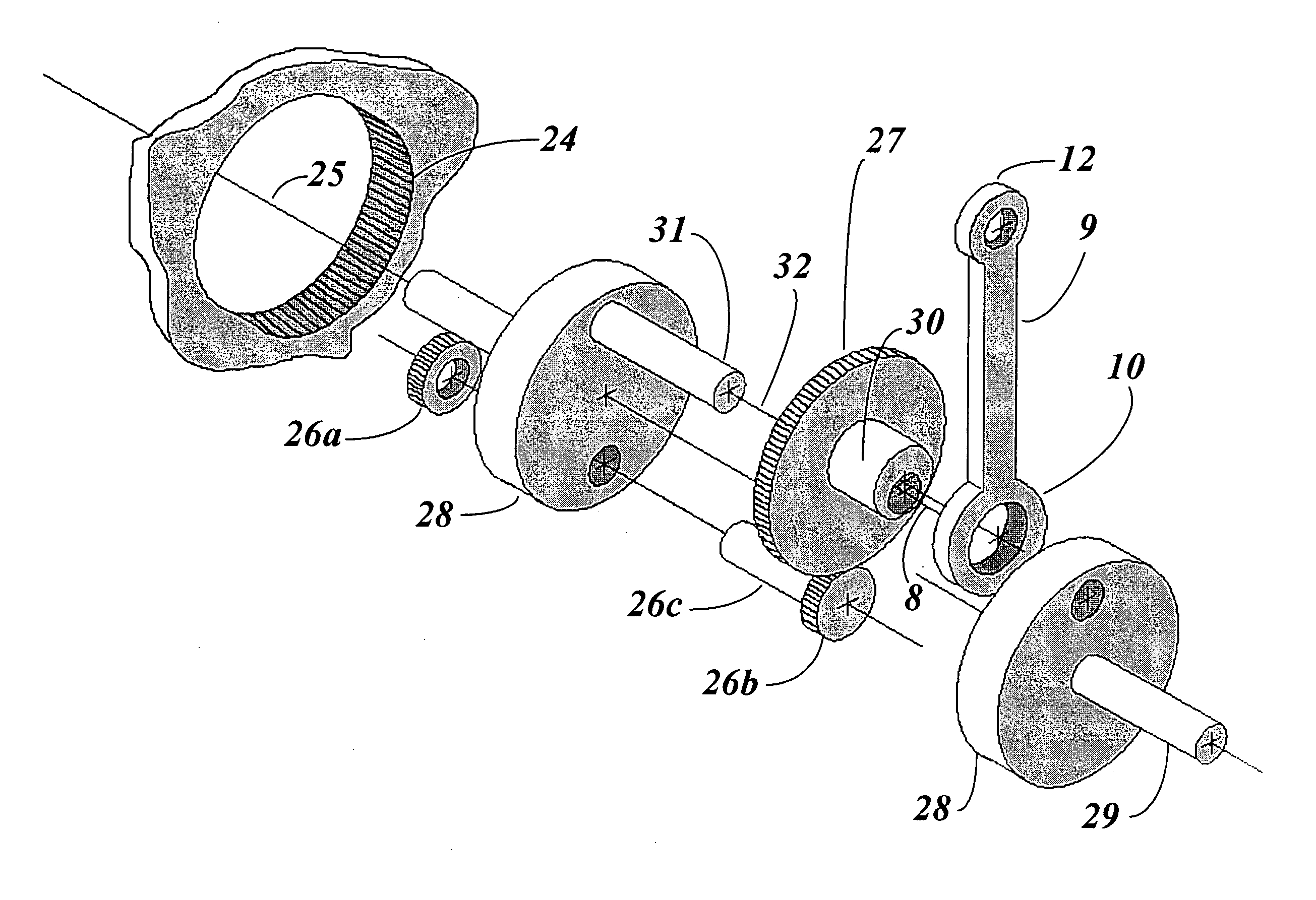
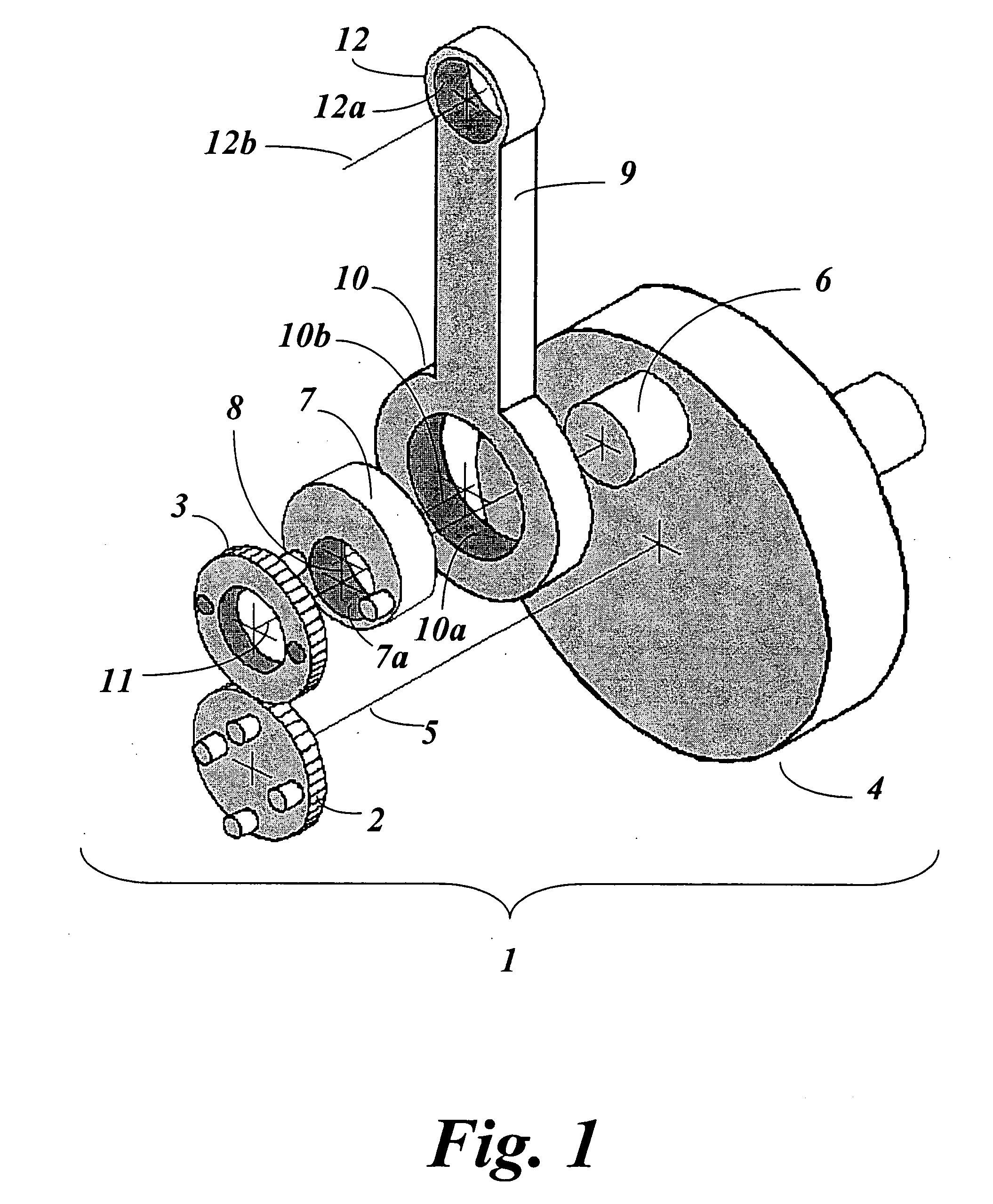
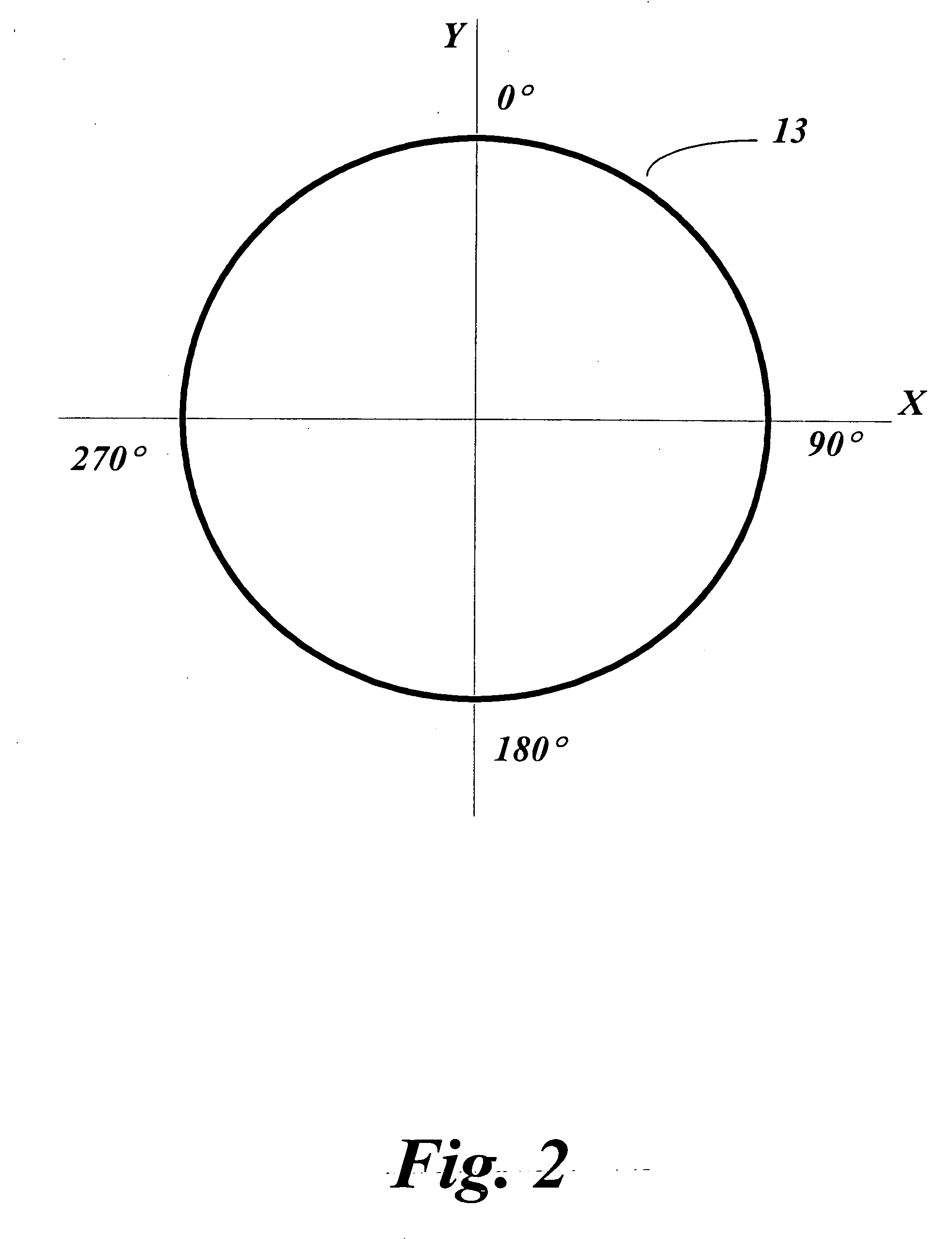
[0065] One embodiment of the inventive Epitrochoidal crankshaft assembly, as depicted in the exploded view shown in FIG. 1, is a simplified planetary gear system 1 utilizing a stationary sun gear 2 and a revolving planet gear 3 of equal pitch diameter. The two gears are kept in constant mesh by a crankshaft 4 that may also serve as a flywheel. The sun gear 2 is fixedly attached to the engine's crankcase, which is not shown, with its axis-5 on the same rotational axis as that of the crankshaft 4. The planet gear 3 is centered on the crankpin 6 by either a bushing or a bearing. These two gears each have a pitch diameter equal to the distance between the axis 5 of the crankshaft 4 and the axis of the crankpin 6, or one-half the stroke of the crankshaft 4. Since the gears are constantly in mesh, the distance between the centers of both gears will never vary; therefore, if the path of the axis 11 of planet gear 3 was plotted as it revolved around the stationary sun gear 2, the resultant ...


PUM


Abstract

This invention relates to a mechanism and method for enhancing the performance of both two stroke and four stroke cycle reciprocating piston internal combustion engines, reciprocating piston pumps and compressors by generating an Epitrochoidal path of travel for the lower end of the connecting rod. The piston, attached to the upper end of the connecting rod, will be made to dwell at the lower part of its travel, enhancing the output of the engine, pump or compressor through better utilization of the available cylinder pressure.

Description

FIELD OF THE INVENTION [0001] This invention relates to a mechanism and method for enhancing the performance of reciprocating piston internal combustion engines, pumps, and compressors by utilizing a crankshaft that generates an Epitrochoidal path. The piston will be made to dwell at the lower part of its travel, enhancing the cylinder output of the engine, pump or compressor through better utilization of available pressure. BACKGROUND OF THE INVENTION [0002] Since the development of the first commercially successful internal combustion engine in the 1860's by Otto and Langen, there have been constant attempts to improve the internal combustion engine. The results of those attempts are apparent everywhere and the internal combustion engine is common throughout the world and used in countless applications, including but not limited to transportation, power generation, construction, agriculture, recreational vehicles, and garden implements, to name a few. In addition to multiple appli...

Claims


Application Information

Patent Timeline
Patent Type & Authority Applications(United States)
IPC IPC(8): F16C3/04
CPCF02B25/24F02B75/048Y10T74/2173F16H21/28Y10T74/2181F02B75/32F16C3/28F16C23/10F16H55/18
Inventor VENETTOZZI, THOMAS MARK
Owner MAROZZI
Why Eureka
Try Eureka