Multi-ionophore membrane electerode

Inactive Publication Date: 2006-03-23
DREW SCI
View PDF2 Cites 35 Cited by
  • Summary
  • Abstract
  • Description
  • Claims
  • Application Information

AI Technical Summary

Benefits of technology

[0055] Varying the relative amounts of two ionophores in a series of sensing membranes can result in a transition from a Class B membrane to a Class A membrane, as the ionophore concentrati

Problems solved by technology

The variable nature of blood or other samples can cause unquantifiable variations in the liquid junction potential, which can give rise to significant errors.
Prolonged exposure to the polyanionic anticoagulant Liquoid resulted in a sensor that was largely unresponsive to chloride ions, due to replacement of the chloride ions by the polyanion species.
The use of the electrode as a reference electrode is limited due to non-equivalen

Method used


Image

  • Multi-ionophore membrane electerode
  • Multi-ionophore membrane electerode
  • Multi-ionophore membrane electerode

Examples


example 1

Flow Cell and Electrode Configuration

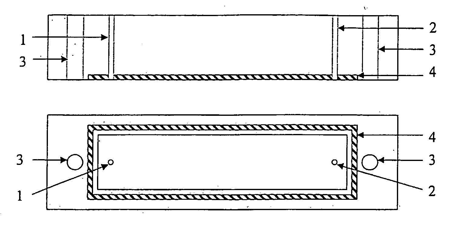
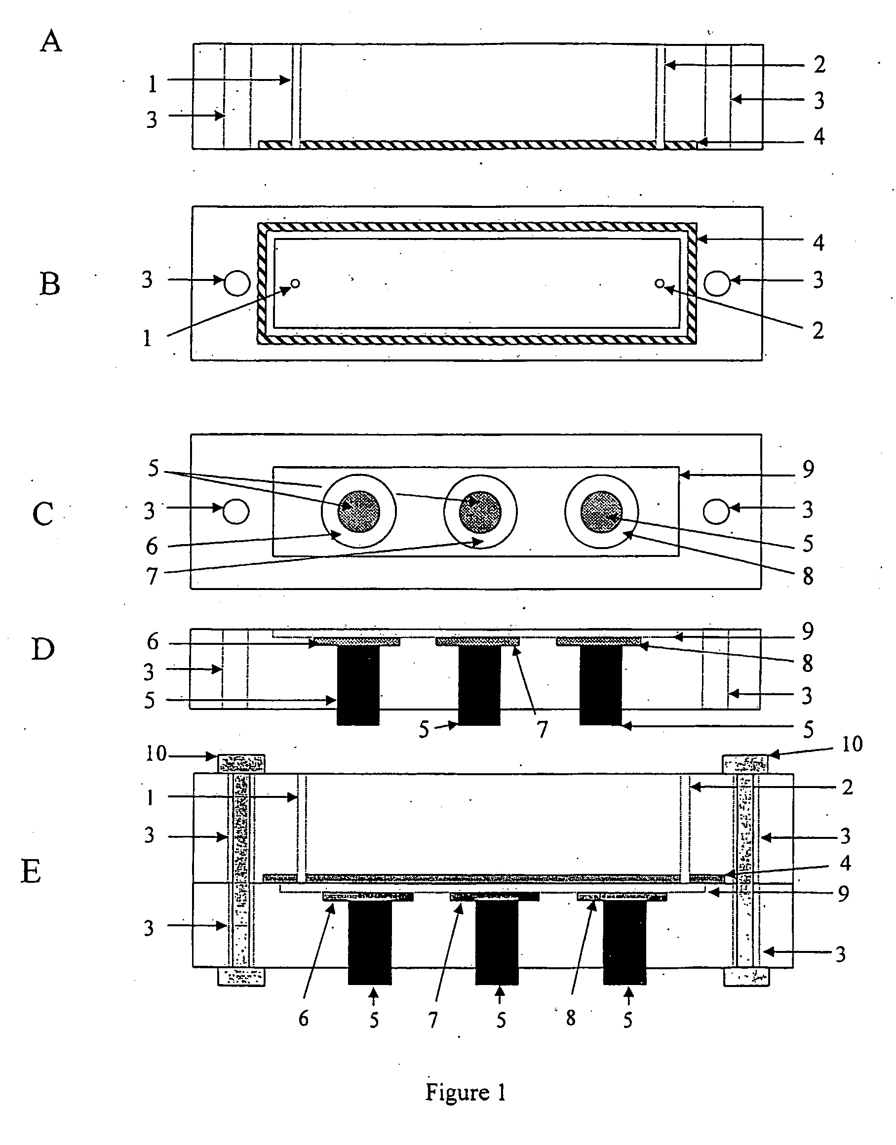
[0078] The potentiometric flow cell was supplied by Drew Scientific, Cumbria, U.K. FIG. 1 shows a sketch of the flow cell, including the sensors.

[0079] The cell is made from polymethacrylate and consists of an upper part shown from the side (A) and from the bottom (B), and a lower part shown from the top (C) and from the side (D). The upper part (A,B) contains an inlet (1) and an outlet (2) for fluid flow, two holes (3) for bolts and a rubber O-ring seal (4). The lower part (C,D) contains carbon rods (5) of about 1 mm diameter and 2 mm length, inserted so that the top of the carbon rod is level with the bottom of the recesses (6, 7 and 8). The recesses are 2 mm diameter, centred on the centre of the carbon rod and have a depth of 0.1 mm. The recesses are filled with ion-sensing membrane solution (such as those prepared in Example 2 below). Suitably recess (6) contains a potassium sensing membrane, recess (7) contains a mixed ionophore membrane ...

example 2

Preparation of Sensors for Sodium and Potassium Ion Sensing Sodium Ion Sensing Membrane Formulation

[0080] PVC (33%), NPOE (66.25%) and sodium tetrafluorophenylborate (0.15%) were weighed into a glass vial and dissolved in 0.5 mL cyclohexanone by heating at 60° C. for 1 hour. The percentage by weight of each membrane component is expressed in terms of weight per total weight of membrane components. To this mixture was added 0.6% METE (methoxyethyl tetraester calixarene) and the mixture was stirred for a further hour. The total weight of the membrane components was 0.17 g.

Potassium Ion Sensing Membrane Formulation

[0081] PVC (33%), bis(2-ethylhexyl) sebacate (64.5%) and KTCPB (0.5%) were weighed into a glass vial and dissolved in 0.5 mL cyclohexanone by heating at 60° C. for 1 hour. To this mixture was added valinomycin (2.0%) and the mixture was stirred for a further hour. The total weight of the membrane components was 0.17 g.

Mixed Ionophore Membrane Formulation

[0082] PVC (32....

example 3

Pseudo-Reference Electrode for Sodium and Potassium Ion Sensors

[0084] Flow analysis was used to determine the response of the sensors to sodium and potassium ion activity over the ranges found in whole blood. FIG. 3 shows the response of the sensors to injections of sample. The predicted potential shift vs. the actual potential shift is shown in FIG. 4.

[0085] The membranes used in the pseudo reference electrode are prepared as set out in Example 2. The sensors were used in the flow cell of FIG. 1, at a flow rate of 120 uL / min with a sample loop size of 300 uL. The carrier composition was 40 mM bis tris (pH 6.95), 0.8 mM Na2EDTA, 140.4 mM NaCl and 4.2 mM KCl. The calibrants were prepared from a buffer containing 40 mM bis tris (pH 6.95) and 0.8 mM Na2EDTA, and had varying amounts of NaCl and KCl to give the total Na+ and K+ concentrations shown in FIG. 3. The concentrations of sodium and potassium ions were chosen to give all combinations of upper and lower limits of reference and ...


PUM


Abstract

A polymeric membrane for ion sensitive measurement comprising a polymer, a lipophilic salt and at least two ionophores selective for different chemical species. The membrane may be used in a pseudo reference for measurement of a plurality of ions.

Description

BACKGROUND OF THE INVENTION [0001] The invention provides a polymeric membrane for ion sensitive measurement and its use in a pseudo reference sensor. INTRODUCTION [0002] The determination of ionic species in samples such as blood using ion selective electrodes is routinely performed with conventional multi-use flow-through analysers and more recently with single-shot or limited re-use disposable sensor cartridges. The former typically make use of a conventional silver / silver chloride reference electrode in a highly concentrated equitransferant solution (typically 3M KCl) with a free-flowing liquid junction or with a diffusion limited junction such as a frit, while the latter often include microfabricated silver / silver chloride electrodes with some surface layer, such as a hydrogel containing a relatively constant concentration of chloride ion. The interface at which the sample and the reference solution or gel meet provides a liquid junction potential. The variable nature of blood ...

Claims


Application Information

Patent Timeline
IPC IPC(8): G01N27/26G01N27/333
CPCG01N27/301G01N27/3335
Inventor MURPHY, LINDYSLATER, JONATHAN M.
Owner DREW SCI
Why Eureka
Try Eureka