Colorant treated ion exchange resins, method of making, heat transfer systems and assemblies containing the same, and method of use

a technology of ion exchange resin and colorant, which is applied in the direction of sustainable manufacturing/processing, thermography, and final product manufacturing, can solve the problems of unsuitable (or not optimized) use of traditional prior art heat transfer systems and heat transfer fluids with alternative power sources, increased corrosion and/or short circuit of electrical current, and electrical shock

Active Publication Date: 2006-03-23
PRESTONE PROD CORP
View PDF29 Cites 19 Cited by
  • Summary
  • Abstract
  • Description
  • Claims
  • Application Information

AI Technical Summary

Benefits of technology

[0128] One gram of colorant saturated resin was added to two 100 g samples of a 50% ethylene glycol aqueous solution respectively containing 30 ppm NaCl or 30 ppm sodium formate+30 ppm sodium acetate. The solutions were stirring constantly with a magnetic bar. The tests were conducted at room temperature. The solution conductivity was measured as a function of time. The following results as set forth in FIG. 2 were obtained. Generally, the solution became red soon after the resin was added into the salt containing solutions. The color became more prominent as time increased, showing that the disclosed colorant-saturated resin is capable of removing the ionic species from the solutions while providing a distinct color to the 50% wt ethylene glycol aqueous solution. This illustrates that colorant treated ion exchange resins made according to the instant disclosures are capable of simultaneously removing ionic species from a 50% ethylene glycol aqueous solution, maintaining low conductivity in the heat transfer fluid solution and providing color to the solution.

Problems solved by technology

Unfortunately, however, traditional prior art heat transfer systems and heat transfer fluids are unsuitable (or not optimized) for use with alternative power sources, especially those employing electricity or an electrical charge.
The use of highly conductive heat transfer fluids with alternative power sources, especially electricity based alternative power sources, can result in electrical shock, increased corrosion and / or the short-circuiting of electrical current.
As a result, conventional heat transfer fluids are unsuitable for use with some alternative power sources; especially electricity based alternative power sources.
However, the presence of an electrical charge makes it challenging to use fuel cells with prior art heat transfer systems and fluids.
However, such metals are vulnerable to corrosion as a result of contact with the heat transfer fluid.
However, many of the corrosion inhibitors previously known for use in internal combustion engine heat transfer fluids are unsuitable for use in fuel cell heat transfer fluids because they are typically highly conductive ionic species.
Such ionic corrosion inhibitors cannot be used in fuel cell heat transfer fluids because of the requirement that fuel cell heat transfer fluids have very low conductivity.
One major drawback of ion exchange resins or electrodeionization cell methods is that they may remove corrosion inhibitors.
As a result, the fuel cell heat transfer fluid may lose its ability to inhibit the corrosion of metal components of the fuel cell heat transfer system.
As a result, the prior art has failed to provide an effective resolution to problems associated with the maintenance of low conductivity in corrosion inhibiting heat transfer fluids for assemblies comprising alternative power sources such as fuel cells.
However, dyes and colorants used in heat transfer fluids intended for use in internal combustion engines are typically highly conductive ionic species.
Such dyes cannot be used in fuel cell heat transfer fluids because of the requirement that fuel cell heat transfer fluids have very low conductivity.
Thus, the use of dyes can be problematic with respect to prior art methods for maintaining low electrical conductivity in heat transfer fluids.
One major drawback of ion exchange resins or electrodeionization cell methods is that they may remove colorants, even very weakly ionically charged colorants and non-conductive colorants.
As a result, the prior art has failed to provide an effective resolution to problems associated with the maintenance of low conductivity in colored heat transfer fluids.

Method used


Image

  • Colorant treated ion exchange resins, method of making, heat transfer systems and assemblies containing the same, and method of use
  • Colorant treated ion exchange resins, method of making, heat transfer systems and assemblies containing the same, and method of use
  • Colorant treated ion exchange resins, method of making, heat transfer systems and assemblies containing the same, and method of use

Examples


example 1

[0112] The conductivity as a function of colorant concentration in de-ionized water at room temperature was evaluated per Table 1. Solutions of the various colorants identified below were mixed in de-ionized water at room temperature under simple agitation. Conductivity was measured via a Traceble® bench conductivity meter manufactured by Control Company, Friendswood, Tex., USA.

TABLE 1Concentration ofColorant in SolutionConductivity of SolutionColorant Name(mg / L)(μS / cm)Uranine1Blank0.30203.36508.2710016.67Liquitint ® Red STBlank0.27200.45500.581000.65Liquitint ® BrightBlank0.28Yellow201.97504.351008.36Liquitint ® Patent BlueBlank0.30201.79503.951007.41Liquitint ® BrightBlank0.28Orange201.11502.231004.05Acid Red 521Blank0.25205.985013.410033.9

1Acid Red 52 is commercially available from Chromatech of Canton, MI. Uranine is commercially available from Honeywell-CPG of Danbury, CT

[0113] It can be seen that the two commonly used antifreeze dyes, i.e., Uranine and Acid Red 52 dye posse...

example 2

[0114] The Liquitint® Red ST dye was also found to be stable at 80° C. in 50% Ethylene glycol+50% de-ionized water (all as volume %). A test was done by dissolving 20 ppm Liquitint® Red into 50% ethylene glycol+50% de-ionized water solution (V / V). The solution was separated into two parts in two clean beakers. One was heated at 80° C. for about 45 minutes. The conductivity of the two solutions before and after the heating was recorded. There was no noticeable change in the solutions. The conductivity of the solution showed essentially no change before and after heating (Blank and before heating at 80° C.: 0.45 μS / cm; kept at 80° C. for ˜45 min and cooled down to room temperature: 0.48 μS / cm).

example 3

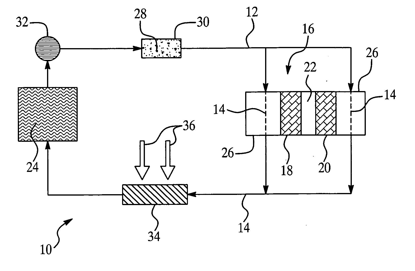
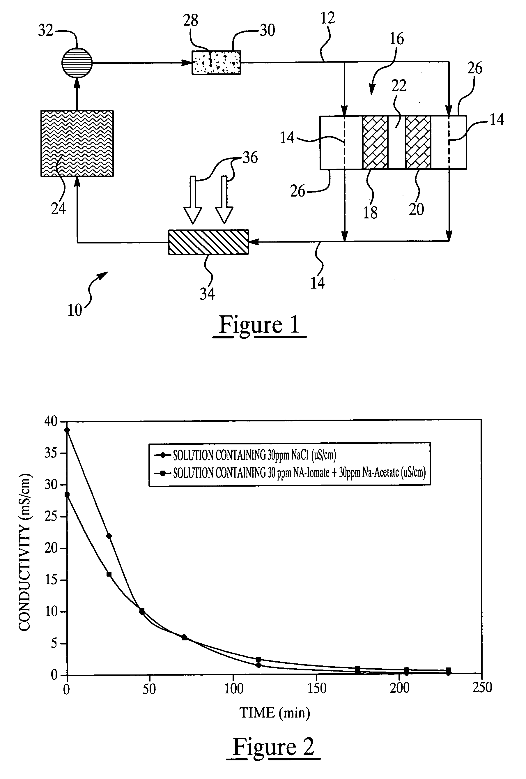
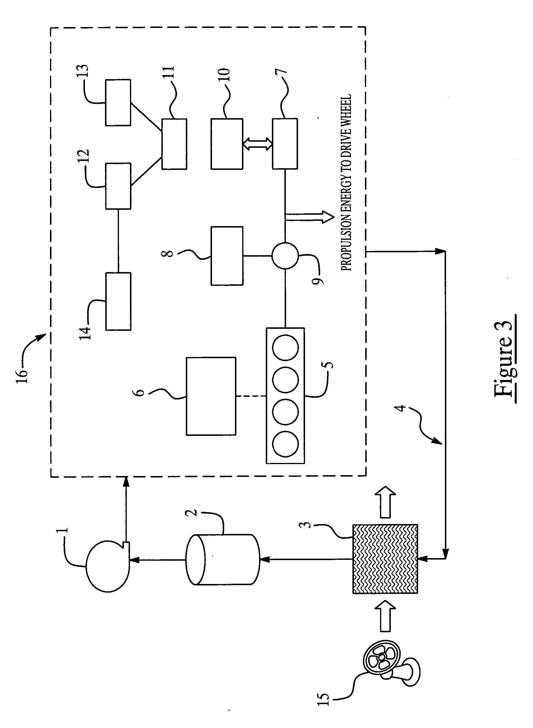
[0115] The effect of the non-conductive dyes upon the corrosion of metals in a fuel cell heat transfer system was evaluated.

[0116] Metal samples according to the following were cleaned with cleaner and de-ionized water before separating into two identical sets and put in 2 clean glass flasks. Each flask contained 4 cast Al coupons, 4 brass coupons, 4 stainless steel (SS316) coupons, 2 brazed Al coupon, 2 silicone gasket, 4 Viton O-rings. The total surface area was about 392 square centimeters. 300 ml 50% ethylene glycol+50% (volume) DI water was added into one flask while 300 ml 50% ethylene glycol+50% (volume) DI water+20 ppm Liquitint® Red ST was added to the second flask.

[0117] The conductivity of each solution was recorded as a function of time. Since corrosion of the metals will generate ionic species and increase the solution conductivity, the conductivity of the solution was used to indicate the extent of the corrosion of the metal samples in the flasks. The results obtaine...


PUM


Abstract

Disclosed is a colorant treated ion exchange resin comprising at least 15% of exchangeable groups comprising at least one of an ion, a Lewis acid, or a Lewis base resulting from a colorant having a pKa or pKb of greater than 5 in an aqueous solution at 25° C., based on the total number of exchangeable groups. Also disclosed are heat transfer systems, assemblies, fuel cell systems and methods of maintaining a conductivity of less than 200 μS / cm in a heat transfer fluid that employ the disclosed colorant treated ion exchange resins. Finally, a method of making the disclosed colorant treated ion exchange resins is provided.

Description

[0001] This application claims the benefit of U.S. Provisional Application Ser. No. 60 / 607,969, filed on Sep. 8, 2004.FIELD OF THE INVENTION [0002] The invention relates to colorant pre-treated ion exchange resins and their use in heat transfer systems, alternative power sources such as fuel cells, and assemblies comprising such power sources. BACKGROUND OF THE INVENTION [0003] Heat transfer systems in thermal communication with a power source have been utilized to regulate heat generated during the operation of the power source. For example, automotive vehicles have employed heat transfer fluids and heat transfer systems that transfer and dissipate heat generated as a by-product of gasoline powered internal combustion engines. In this case, the heat transfer fluids and heat transfer systems ensure that the engine operates in an optimum environment and is not subject to undesirably high temperatures. [0004] However, alternatives to traditional gasoline powered internal combustion en...

Claims


Application Information

Patent Timeline
Patent Type & Authority Applications(United States)
IPC IPC(8): H01M8/04H01M8/12
CPCB01J47/006C09K5/10F01P2011/068F28F19/00Y02E60/522H01M8/04029H01M8/04059Y02E60/523Y02E60/50H01M8/04007B01J47/016Y10T428/249921Y02P70/50B01J47/00H01M8/04H01M8/12
Inventor YANG, BOWOYCIESJES, PETER M.MARINHO, FILIPE J.GERSHUN, ALEKSEI V.
Owner PRESTONE PROD CORP
Why Eureka
Try Eureka