Self-actuating and regulating heat exchange system

Inactive Publication Date: 2006-03-30
ALAM MOHAMMED
View PDF14 Cites 30 Cited by
  • Summary
  • Abstract
  • Description
  • Claims
  • Application Information

AI Technical Summary

Benefits of technology

[0020] An advantage of the present invention it that it is very efficient and convenient for transporting heat over greater distances than has been feasible with in prior devices.
[0021] Another advantage of the inventive system is that it provides much greater flexibility in the relative placement of heat sink and condenser elements.
[0022] Yet another advantage of the inventive system is that it has higher rate of heat transfer due to the combination of liquid vapor phase-change heat transfer methodology and stronger condensate return force.
[0023] Still another advantage is that the inventive system can keep the heat

Problems solved by technology

Some of these devices and components, such as electronic circuit board components and semiconductor chips, present special problems due to their relatively small size, rapid heat buildup and compact installation parameters.
When properly installed, either of these devices has proven to work effectively; however each has specific disadvantages of its own.
The thermosiphon has a major limitation as its operation and performance is dependent on gravity and relative position of its components.
Consequently, if the evaporator is located above the condenser the working fluid liquid will not come back to the evaporator, thus the machine will not work.
This is why a thermosiphon cannot work for a system where the thermal energy is required to be transferred against the gravitational force.
Furthermore, if the location of heat source is above the heat-sink relative to gravity, the thermosiphon will not work.
This also implies that a thermosiphon system will not work where the gravity is low or does not exist.
In addition to the relative position of evaporator and condenser, the second

Method used


Image

  • Self-actuating and regulating heat exchange system
  • Self-actuating and regulating heat exchange system
  • Self-actuating and regulating heat exchange system

Examples


Example

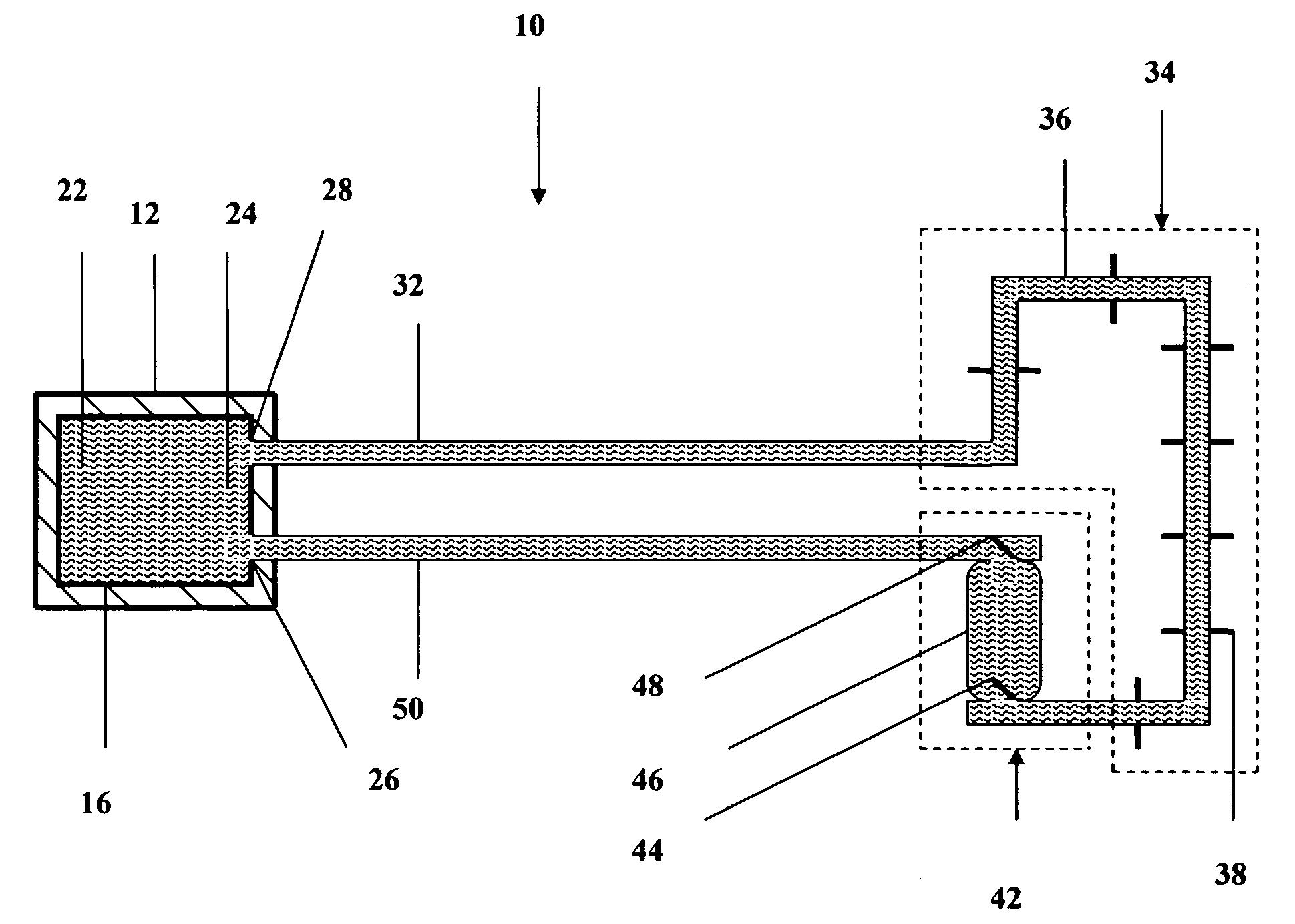
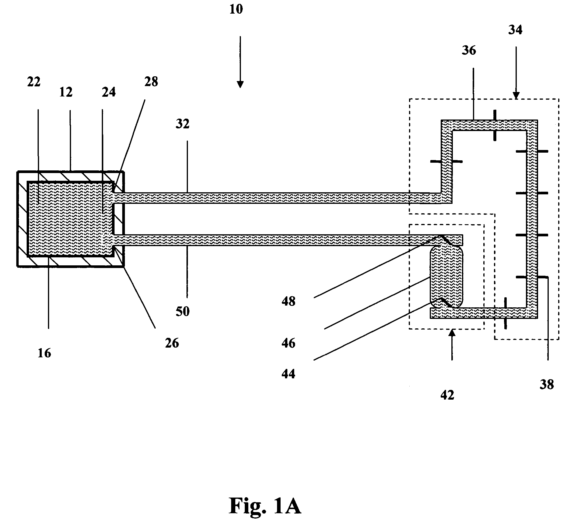
[0037] A preferred embodiment of the present invention is a heat exchange system and method suitable for use in a variety of applications where maintenance of temperature in an operational component is desirable. A particularly preferred embodiment, adapted for use with semiconductor chips is shown in the several figures of the drawing and is designated by the general reference character 10. One of the intentions of the present invention is to use in electronic and circuit board applications. The applicability of the present invention either for cooling an electronic chip, or cooling any other hot devices are very similar, even though for simplicity to describing, electronic chip is repeatedly mentioned.

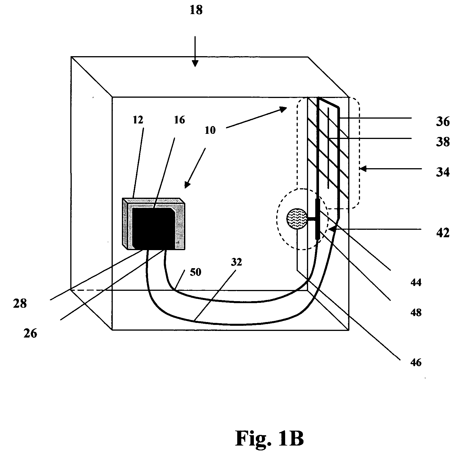
[0038] Referring now to FIG. 1A and FIG. 1B are tow different views of the preferred embodiment of the heat exchange system 10 is shown in a stylized illustration. Refer to FIG. 1B, the system 10 is adapted for use with an electronic component-box 18 and is illustrated as mounted on...


PUM


Abstract

A self-actuating and self regulation heat exchange system comprising: evaporator 16, condenser 34, bladder sub-system 42, phase-change fluid 24 and connecting tubes, is a device and an apparatus useful to transport thermal energy from a relatively hot zone to a relatively cold zone, over distance, and around or through obstructions. The bladder sub system, consisting of an expandable bladder and two one-way check-valves, utilizes the pressure difference in the system created during evaporation and condensation to make the phase-change fluid circulate inside the closed loop system, transferring thermal energy from evaporator to condenser. The operation of the device is self started, self regulated and the device is almost independent of gravity, and the orientation.

Description

[0001] This application claims the benefit of provisional patent application 60 / 606,056, filed 31 Aug. 2004 to USPTO by the same inventor.TECHNICAL FIELD [0002] This present invention relates generally to mechanisms which transport thermal energy and more particularly, cooling systems used with electronic, electrical, mechanical, chemical or other heat producing components. BACKGROUND ART [0003] Many operating devices need cooling to operate smoothly and efficiently. Some of these devices and components, such as electronic circuit board components and semiconductor chips, present special problems due to their relatively small size, rapid heat buildup and compact installation parameters. Various devices, generally referred to as heat sinks, are utilized in order to keep the components within prescribed temperature ranges so they are able to operate continuously and efficiently without damage to the elements and circuitry. [0004] The increasing importance of thermal transport technolo...

Claims


Application Information

Patent Timeline
IPC IPC(8): H05K7/20
CPCG06F1/20G06F1/206H01L23/427F28D15/0266H01L2924/0002H01L2924/00
Inventor ALAM, MOHAMMED
Owner ALAM MOHAMMED
Why Eureka
Try Eureka