Method and system for signal and power distribution in a building housing a manufacturing process

Inactive Publication Date: 2006-04-06
NCC NANO LLC
View PDF3 Cites 15 Cited by
  • Summary
  • Abstract
  • Description
  • Claims
  • Application Information

AI Technical Summary

Benefits of technology

[0008] A facility power distribution system comprises conductive cable enclosures that may be suspended overhead in a facility. The enclosures or cable trays are partitioned into two or more shielded channels depending on the range of power levels of voltages and signals being distributed. The cable trays are single point grounded to the building ground and provide low impedance distributed grounding over the facility area. Signal and power feeds are dropped orthogonal to the cable trays extending connections of high or low power signals to floor level for atta

Problems solved by technology

Noise and interference can lower accuracy of measurements or lead to malfunctions especially with electromechanical systems that use low level logic and sensor signals to control operations.
These high currents generate voltage drops that become noise in the form of ground level voltage shifts.
It is very difficult to provide a flexible way to construct facility power distribution so that equipment and control circuitry may be added while maintaining quality low level signal integrity and a high level of isolation from interference between functional units.
The resources expended to minimize signal cross talk in many pulsed power systems can represent a significant fraction of the overall system cost.
Low level diagnostic signals are routinely carried by expensive shielded cables.
Shielding on these cables is not effective in suppressing very low frequency noise.
Despite these efforts, considerable effort is frequently wasted t

Method used


Image

  • Method and system for signal and power distribution in a building housing a manufacturing process
  • Method and system for signal and power distribution in a building housing a manufacturing process
  • Method and system for signal and power distribution in a building housing a manufacturing process

Examples


Embodiment Construction

[0020] In the following description, numerous specific details are set forth to provide a thorough understanding of the present invention. However, it will be obvious to those skilled in the art that the present invention may be practiced without such specific details. In other instances, well-known circuits and devices may be shown in block diagram form in order not to obscure the present invention in unnecessary detail. For the most part, details have been omitted inasmuch as such details are not necessary to obtain a complete understanding of the present invention and are within the skills of persons of ordinary skill in the relevant art.

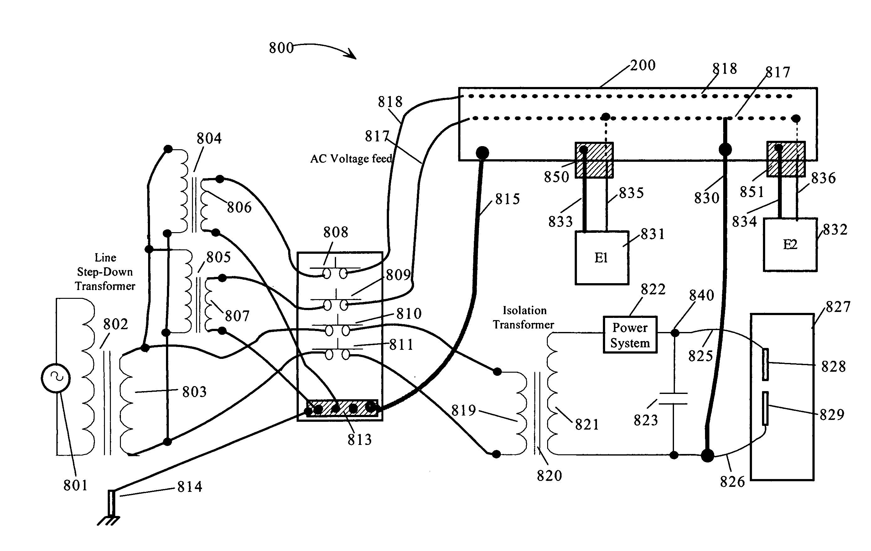
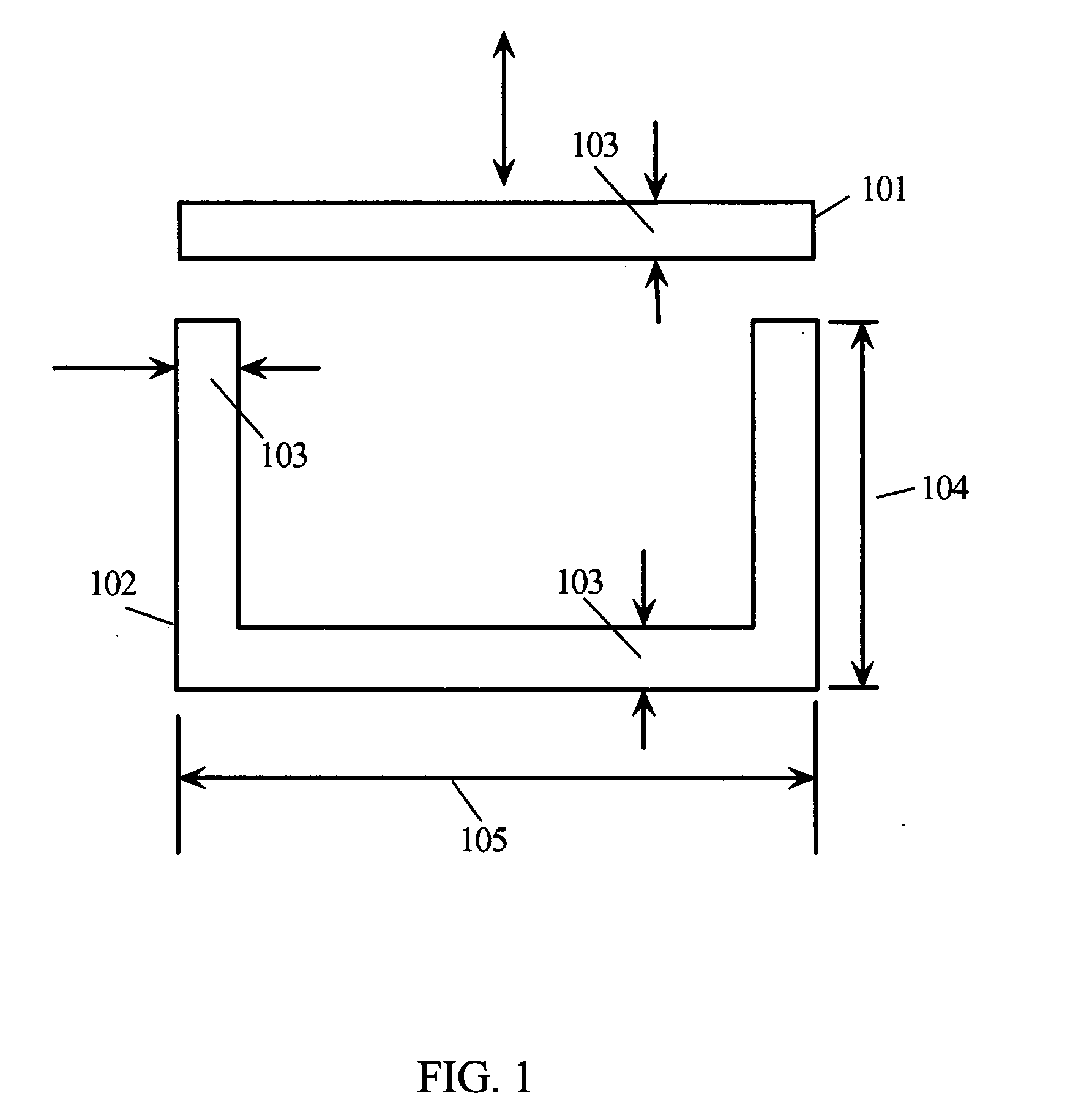
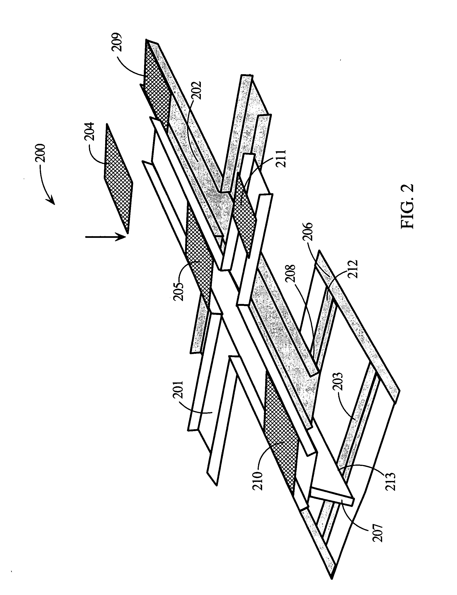
[0021] The cable distribution system described herein employs channels. Channels are configurations with a length substantially greater than their width. The enclosed channels in the following descriptions are configured to direct the routing of cables from one device to another device or from a source of power to the devices utilizing the power...


PUM


Abstract

A power and signal distribution system is adaptable to existing building areas and provides a shielded, low resistance and low inductance grounding structure. The distribution system comprises two or more electrically conductive enclosed channels; one for lower current signals and power distribution and one for high current signals and power distribution. The enclosed channels are electrically coupled and are configured as crosses or spokes with branches extending substantially over the length and width of the building area. The earth ground for the building has a direct connection to one of the enclosures. The ground of each device in the building area is directly connected to the enclosed channels by a low impedance connection. Cables are routed through the enclosures and extended to the devices. The walls of the enclosed channels have a thickness that is greater than the skin depth of a predetermined low frequency.

Description

TECHNICAL FIELD [0001] The present invention relates in general to configuring power distribution so that high power signals and power feeds have minimum coupling to low power signals and power feeds. BACKGROUND INFORMATION [0002] Many facilities and especially laboratories provide some method to ensure signal integrity when they have the occasion to operate high power equipment that uses electronics and sensors for controlling operations. These methods incorporate some forms of power distribution configuration, shielding, transformer isolation, etc., in an attempt to minimize noise and interference. Noise and interference can lower accuracy of measurements or lead to malfunctions especially with electromechanical systems that use low level logic and sensor signals to control operations. Some buildings are constructed with special ground planes that have their own isolated connection to earth ground with a conductive stake or stakes. Instrumentation and low level circuitry is then g...

Claims


Application Information

Patent Timeline
IPC IPC(8): H02H9/06
CPCH02G3/0437H05K9/0064
Inventor SCHMIDT, STEPHEN JAMESMCCOOL, STEVEN C.
Owner NCC NANO LLC
Why Eureka
Try Eureka