
Power converter

a technology of power converters and converters, applied in the direction of motor/generator/converter stoppers, dynamo-electric converter control, instruments, etc., can solve the problems of heat dissipation, noise generation, and the face of the converter, so as to avoid the unfavorable drop in the speed of the fan under heavy load conditions and achieve high breakdown voltage

Active Publication Date: 2006-04-20
PROGRESSIVE DYNAMICS
View PDF55 Cites 40 Cited by
  • Summary
  • Abstract
  • Description
  • Claims
  • Application Information

AI Technical Summary

Benefits of technology

[0010] In the preferred embodiment described herein, the converter further comprises a transformer for stepping voltages within the converter circuit down to a level suitable for use in connection with dc load devices and the charging of conventional storage batteries. Most of the reference voltages in the converter are taken from the primary side of the transformer. In addition, the fan supply and fan control are on the primary side of the transformer. By supplying the fan from the primary side, an undesirable drop in fan speed under heavy load conditions is avoided.
[0014] The converter of the present invention, like the converter described in the '066 patent, uses a metal heat sink as part of the converter packaging structure and mounts certain components on or in contact with the heat sink. A thermistor sensor, preferably mounted on or in contact with the heat sink, is used to monitor converter temperature and provide an output signal which, also unlike the '066 patent converter, is simultaneously supplied to two control circuits. The first control circuit operates the fan in a variable speed mode. These modes of operation are believed to not only extend fan life, but also reduce an annoying quality of fan noise. The thermistor sensor also furnishes a temperature-related signal to a second circuit including a comparator or “op-amp” to shut down the variable duty cycle controller in the event of a high temperature condition which may exceed the capacity of the fan.
[0015] Other aspects of the invention in the area of thermal control include a special mounting arrangement between the fan motor and the extrusion which provides the heat sink; i.e., a recess is machined into an end of the heat sink extrusion to provide an air gap between the extrusion and the fan motor so that the fan motor does not directly pick up heat from the extrusion. In addition, heavy wire leads are used in overlying relationship to the copper plating of a circuit board used to mount the elements of the circuit of FIG. 2. The wire leads are soldered to the board in high current connector areas. Numerous advantages flow from these packaging modifications as will be hereinafter explained in greater detail.

Problems solved by technology

A designer of such converters faces numerous issues including heat dissipation, noise generation, tolerance to unstable or excessive supply voltages and protection of the expensive circuit components found therein.
The manufacturer of such devices faces these and other issues including warranty claims based on alleged defects when, in fact, field failures are often caused by improper use such as (1) accidentally connecting the converter input to an excessive voltage source such as a 220 vac line or an improperly regulated or runaway generator; and (2) accidentally connecting the RV battery in reverse polarity

Method used


Image

  • Power converter
  • Power converter
  • Power converter

Examples


Embodiment Construction

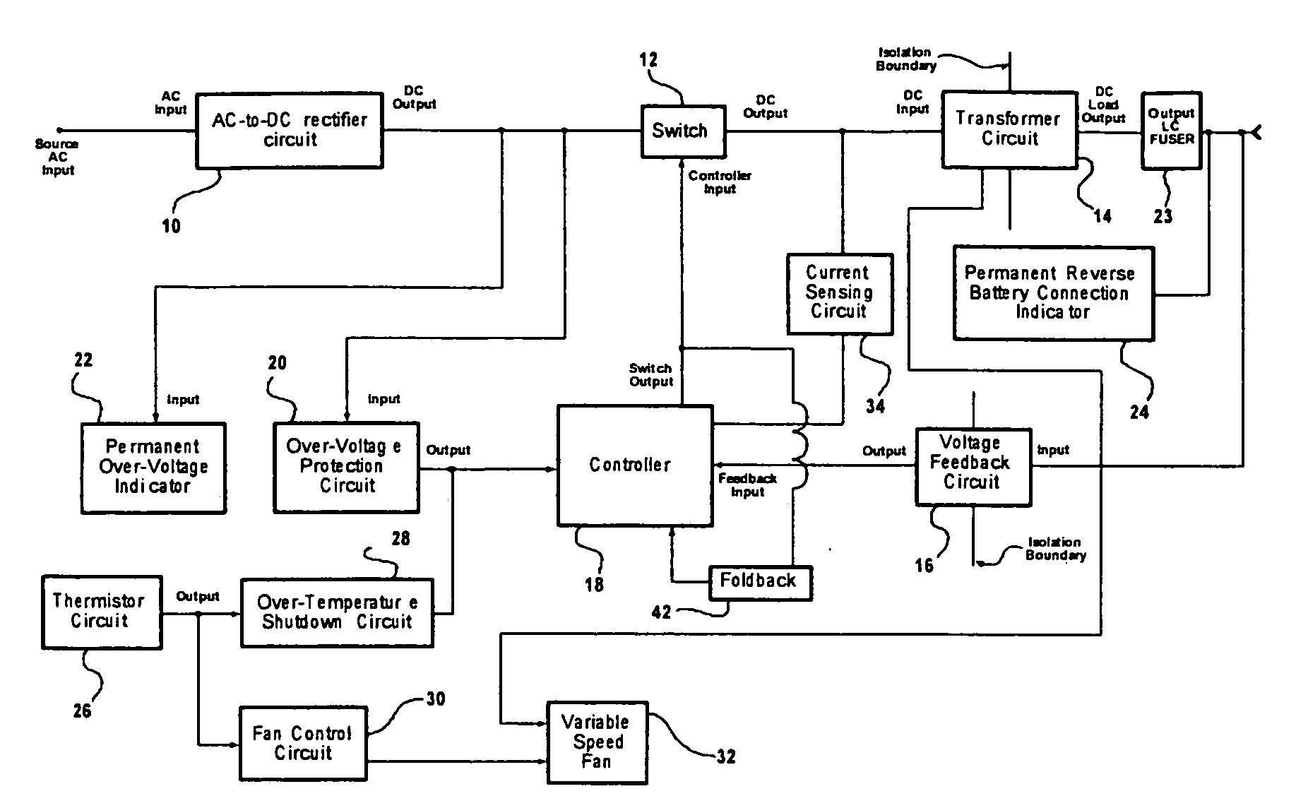
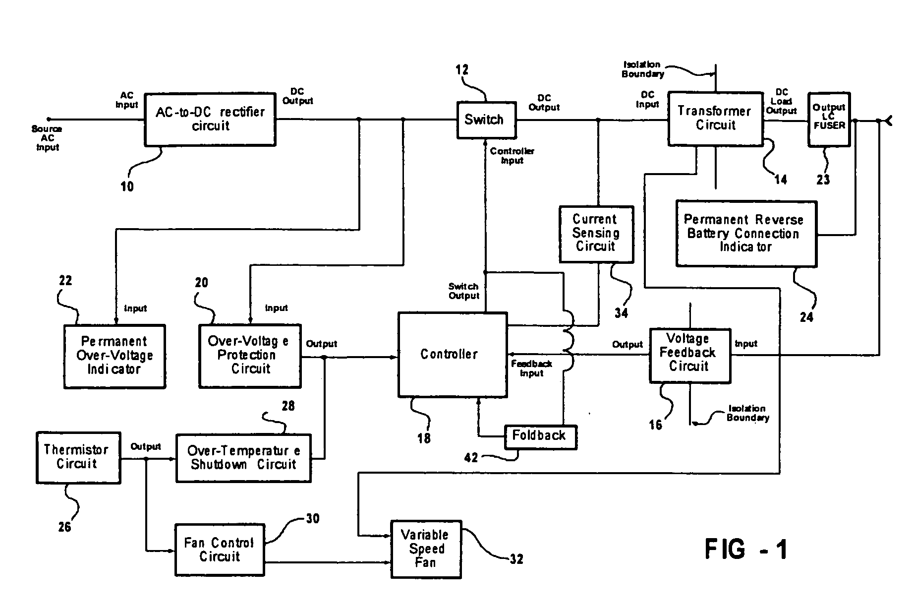
[0043]FIG. 1 is a block diagram of a circuit for a switched power converter embodying the features of the present invention. The block diagram includes an AC-to-DC rectifier circuit 10, a switch circuit 12, a transformer circuit 14, a feedback circuit 16, a controller 18, an over-voltage shutdown circuit 20, a permanent over-voltage indicator 22, a permanent reverse battery indicator 24, a thermistor circuit 26, a variable speed fan 32, fan control circuit 30, an over-temperature shutdown circuit 28, a current sensing feedback circuit 34, a foldback circuit 42, and an output rectifier and LC filter circuit 44 including the inductor L2 referred to hereinafter.

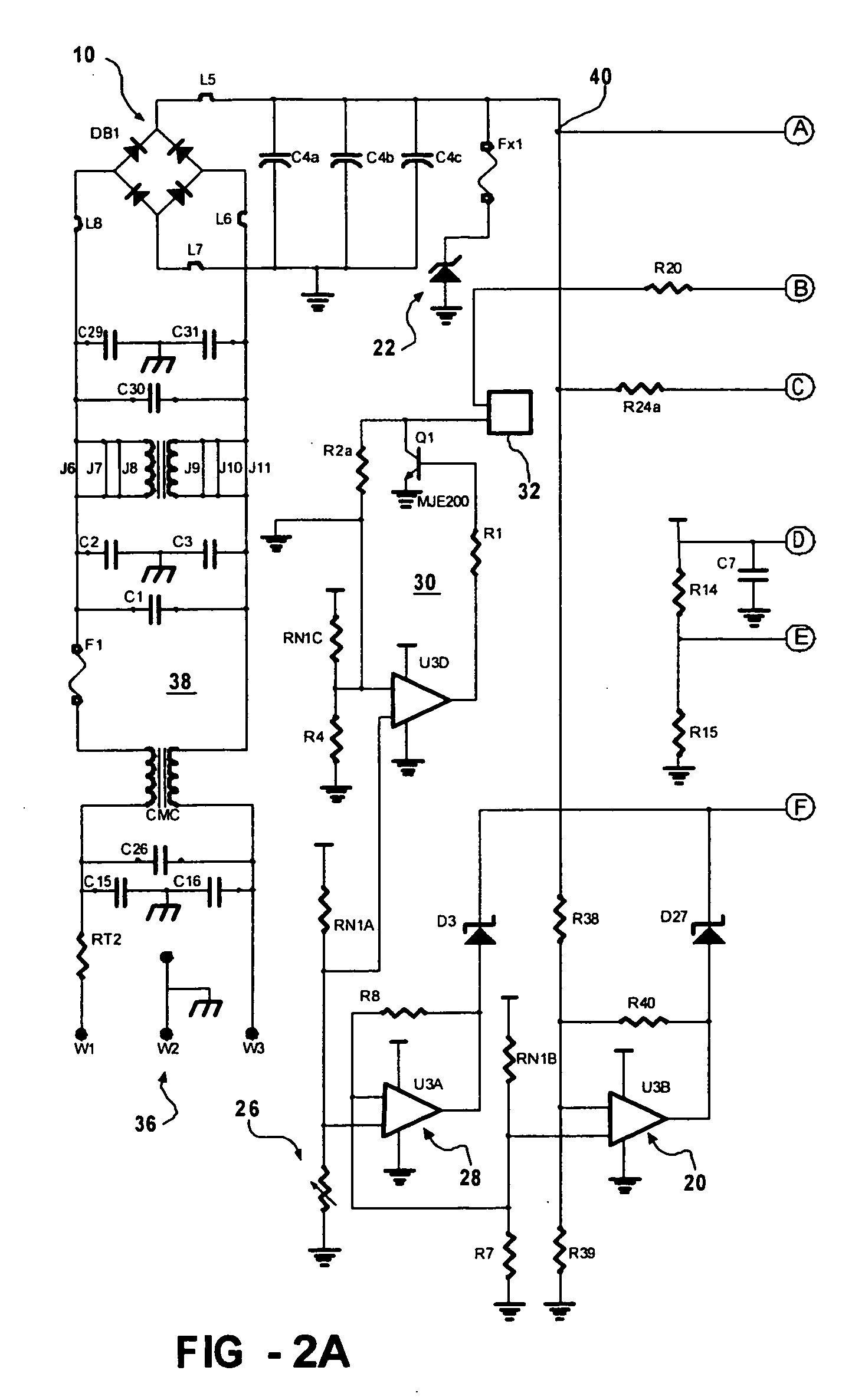
[0044] The AC-to-DC rectifier circuit 10 converts a 115 v AC line voltage into an unregulated and time-varying dc signal with an average in the 170 volt range. It should be noted that the converter 46 can be plugged into a 170 vdc source, if available. In this case the rectifier 10 performs no rectification functions. The unreg...


PUM


Abstract

A switch-type power converter comprising an FET switch operating in a variable duty cycle mode under the control of a Unitrode 3846 integrated circuit controller. Indications of excess input voltage and reverse battery connections are provided by circuits including an element which permanently changes state. A cooling fan mounted on a finned heat sink is operated in a variable speed mode. A single thermistor sensor provides inputs to both the fan speed control and a thermal shutdown circuit connected to shut down the gate drives to the FET switch in the event of a high temperature condition. Another shutdown function is provided in response to an input overvoltage condition by way of an operational amplifier. The converter uses foldback for short circuit protection and is compatible with microprocessor units to selectively provide multiple output voltage levels.

Description

RELATED APPLICATION [0001] This application claims priority in part to provisional application Ser. No. 60 / 607,950 filed under attorney docket no. PDY-106-A on Sep. 9, 2004.FIELD OF THE INVENTION [0002] This invention relates to power converters, and more particularly to switch-type power converters designed for use in recreational vehicles as a regulated power supply for DC load devices and as a battery charger. BACKGROUND OF THE INVENTION [0003] As used herein, the terms “recreational vehicle” and “RV” should be construed to embrace motor homes, trailers, campers, van conversions, fifth wheels, boats, and similar products. The common characteristic of these recreational vehicles is an electrical system incorporating one or more batteries to provide power for DC load devices such as lights, refrigerators and motors. The more sophisticated recreational vehicles may also have alternating current systems and AC load devices such as stoves, televisions, microwaves and heating and venti...

Claims


Application Information

Patent Timeline
Patent Type & Authority Applications(United States)
IPC IPC(8): H02M3/335
CPCH02M1/32H02M3/28Y10S388/934
Inventor COOK, JAMES C. II
Owner PROGRESSIVE DYNAMICS
Learn More