Optical signal amplification device
- Summary
- Abstract
- Description
- Claims
- Application Information
AI Technical Summary
Benefits of technology
Problems solved by technology
Method used
Image
Examples
embodiment 1
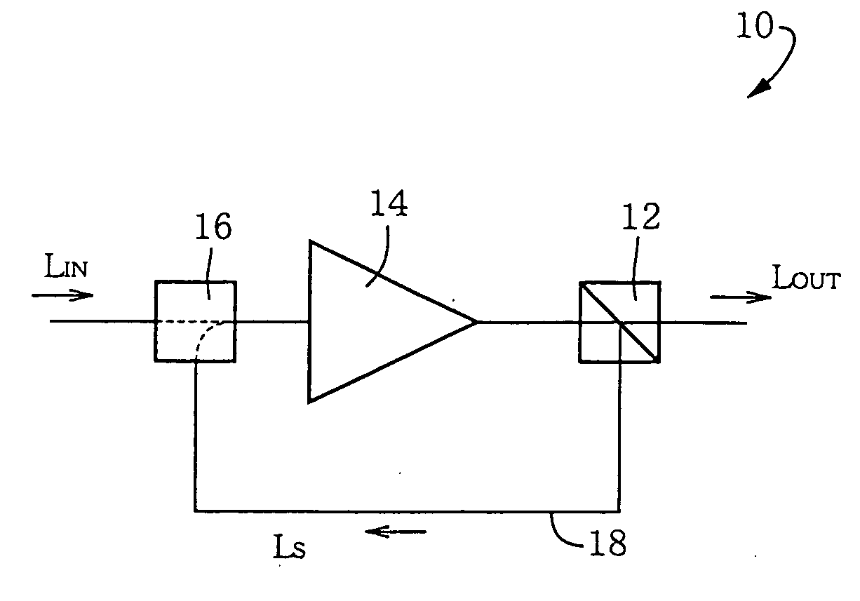
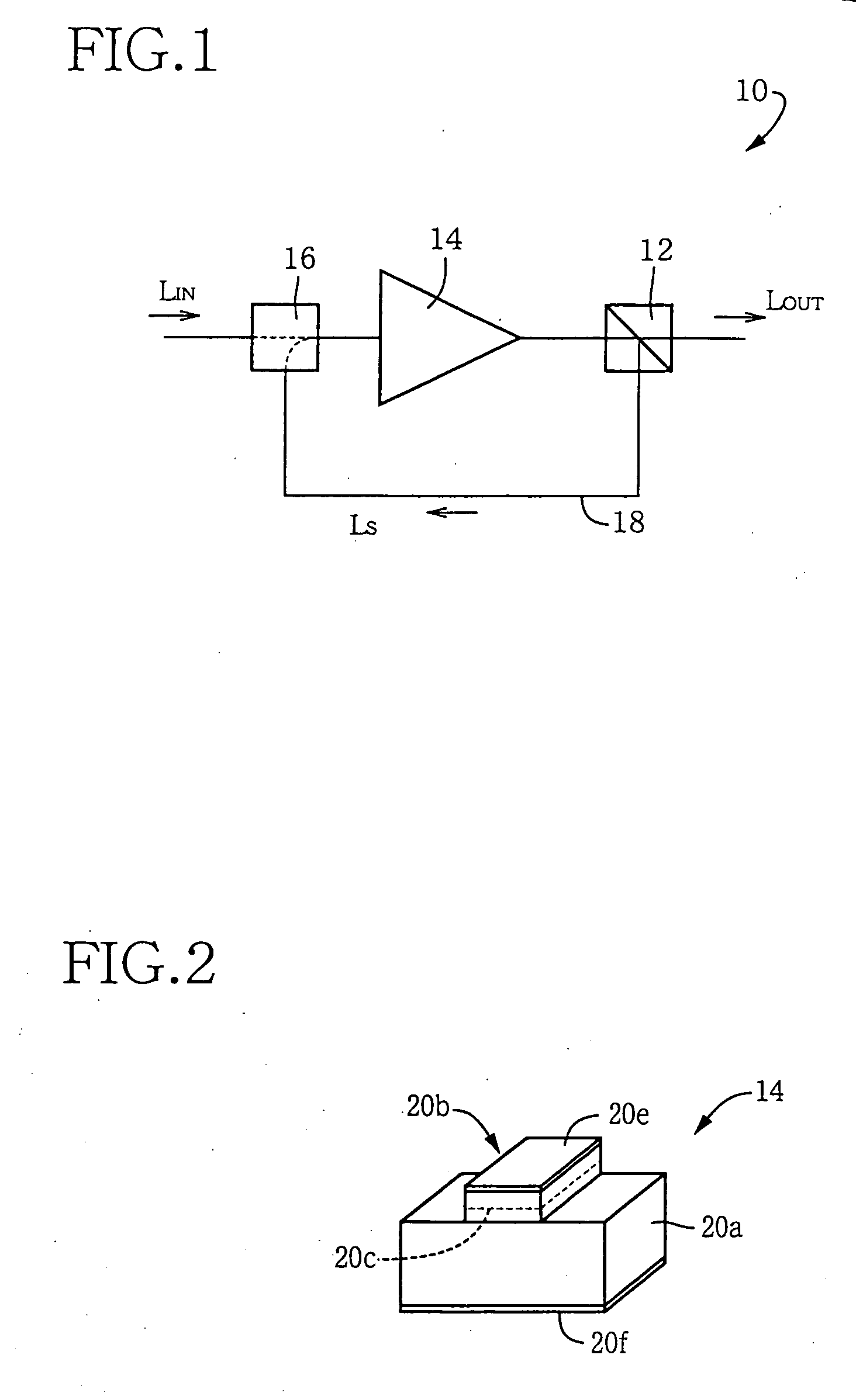
[0056] Referring to the drawings, there will be described in detail an optical signal amplification device 10 of one embodiment of the present invention which is equipped with a negative feedback amplification function.
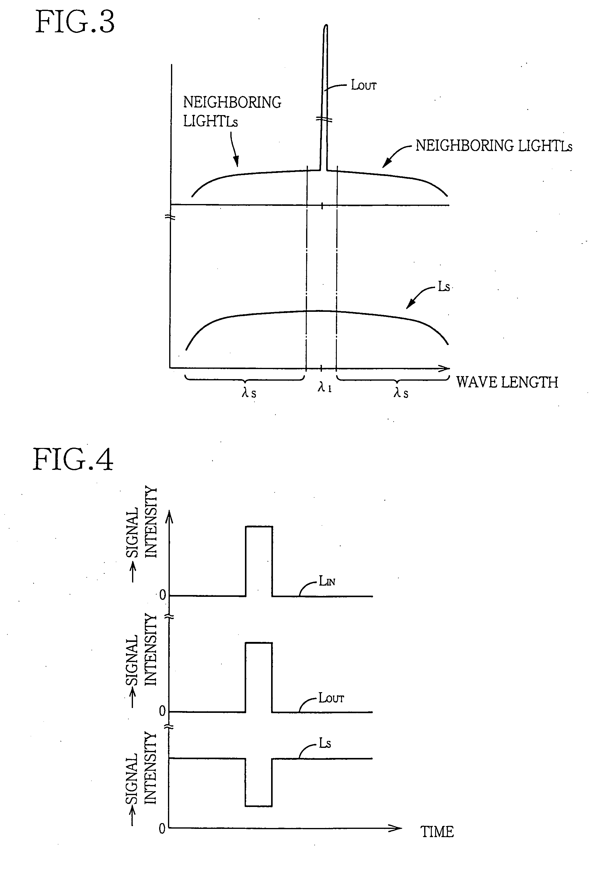
[0057] In FIG. 1, there is shown a wavelength selecting element 12, which is provided to extract, from an output light outputted from a first optical amplifying element 14, an output signal light LOUT of a first wavelength λ1 of, for example, 1550 nm and a neighboring light LS having a wavelength other than the first wavelength λ1. That is, the wavelength selecting element 12 renders the light having a predetermined wavelength of 1545-1555 nm (whose central value is 1550 nm) to be transmitted therethrough, while reflecting all or a part of the light having a wavelength λS (i.e., a predetermined wavelength band corresponding to a range of λSS>1555 nm) that is other than the above-described predetermined wavelength. This wavelength selecting element 12 may be constitut...
embodiment 2
[0063] Next, there will be described other embodiments of the present invention. In the following embodiments, the same reference signs as used in the above-described embodiment will be used to identify the common parts, and description of these parts will not be provided.
[0064]FIG. 5 shows a monolithic arrangement as another example in which the above-described optical signal amplification device 10 is mounted on a single semiconductor chip. In FIG. 5, on a semiconductor substrate 28a, there is formed a waveguide 28b, which consists of a straight portion and an elliptic portion that overlaps with a central part of the straight portion so as to be connected with the straight portion. An upper electrode 28c is provided in a portion of the waveguide 28b, which portion corresponds to the central part of the straight portion and a part of the elliptic portion, so as to function as the above-described first optical amplifying element 14. A wavelength selecting element 30, having a refra...
embodiment 3
[0065]FIG. 6 is a view explaining the construction of an optical signal amplification device 42 of another embodiment of the present invention. In FIG. 6, the neighboring light LS, which has been separated by the wavelength selecting element 12, is inputted to a second optical amplifying element 44 via the optical feedback path 18. The neighboring light LS is amplified in the second optical amplifying element 44, and is then coupled with the input signal light LIN in an optical coupler 46, so that the neighboring light LS, together with the input signal light LIN, is inputted to the first optical amplifying element 14. Unlike the wavelength selecting element 12, the optical coupler 46 does not have to be provided by a filter, as long as it is capable of coupling the output light of the second optical amplifying element 44 and the input signal light LIN with each other. However, the optical coupler 46 may be provided by the above-described optical add / drop filter or the like. As desc...
PUM
 Abstract
Description
Claims
Application Information
 - R&D
- Intellectual Property
- Life Sciences
- Materials
- Tech Scout
- Unparalleled Data Quality
- Higher Quality Content
- 60% Fewer Hallucinations
Browse by: Latest US Patents, China's latest patents, Technical Efficacy Thesaurus, Application Domain, Technology Topic, Popular Technical Reports.
© 2025 PatSnap. All rights reserved.Legal|Privacy policy|Modern Slavery Act Transparency Statement|Sitemap|About US| Contact US: help@patsnap.com


