Complex filter circuit and receiver circuit

a receiver circuit and filter circuit technology, applied in the field of wireless communication systems, can solve the problems of significant degradation of the image rejection ratio, the inability to compensate for the gain error and the image rejection ratio of the complex filter circuit. achieve the effect of improving the image rejection ratio

Inactive Publication Date: 2006-04-27
PANASONIC CORP
View PDF10 Cites 18 Cited by
  • Summary
  • Abstract
  • Description
  • Claims
  • Application Information

AI Technical Summary

Benefits of technology

[0009] In view of the problems set forth above, it is an object of the present invention to reduce an IQ mismatch, thereby improving an image rejection ratio, in a complex filter circuit and in a quadrature-modulated signal receiver circuit using the same.

Problems solved by technology

However, setting these element values to small values increases an IQ mismatch, which is a mismatch between an element in the I signal processing portion of the complex filter circuit and the corresponding element in the Q signal processing portion thereof, thus degrading the image rejection ratio of the complex filter circuit.
Since the influence of the IQ mismatch is significant over the image frequency band, even a very slight error in an element may lead to a significant degradation of the image rejection ratio.
Specifically, the conventional methods aim at reducing the phase error in the local oscillator signal input to the quadrature demodulator because a phase error of the local oscillator signal leads to a phase error of the I and Q signals.
With these conventional methods, however, it is essentially difficult to compensate for the gain error in the complex filter circuit.
Moreover, it is expected that pursuing further reductions in the power consumption and the circuit area of a complex filter circuit will result in the characteristics degradation due to an element error being more serious than that due to the phase error of the local oscillator signal.

Method used


Image

  • Complex filter circuit and receiver circuit
  • Complex filter circuit and receiver circuit
  • Complex filter circuit and receiver circuit

Examples


first embodiment

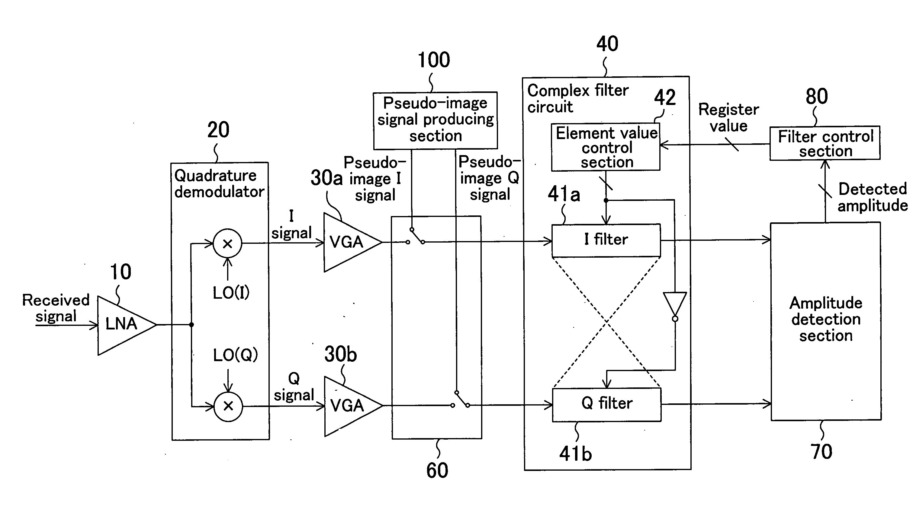
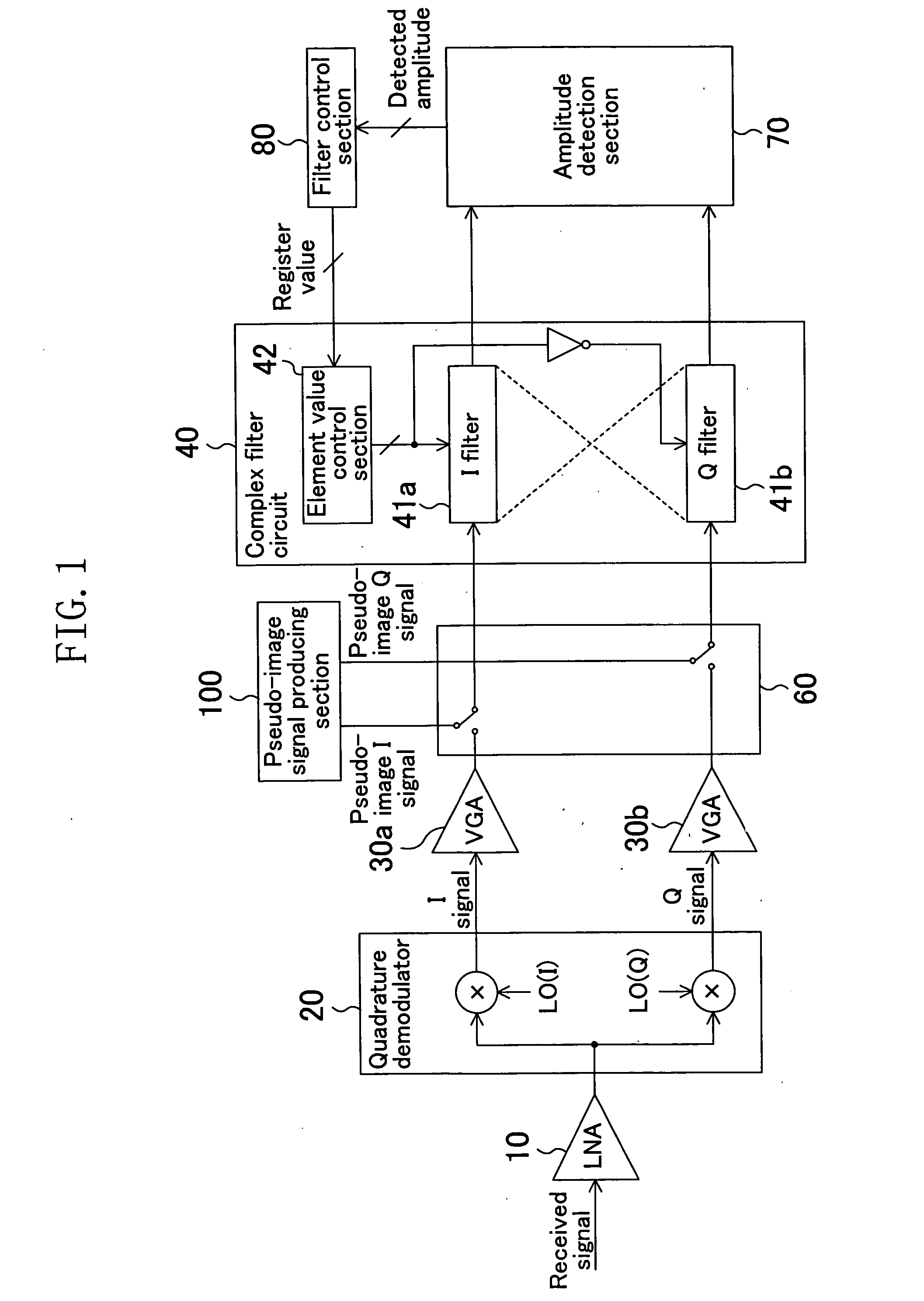
[0030]FIG. 1 shows a configuration of a receiver circuit according to a first embodiment of the present invention. The receiver circuit of the present embodiment includes an LNA 10, a quadrature demodulator 20, VGAs 30a and 30b, a complex filter circuit 40, a signal switch 60, an amplitude detection section 70, a filter control section 80, and a pseudo-image signal producing section 100. Elements characteristic of the present invention will now be described in detail. Note that like elements to those of the conventional receiver circuit shown in FIG. 14 will be denoted by like reference numerals and will not be further described below.

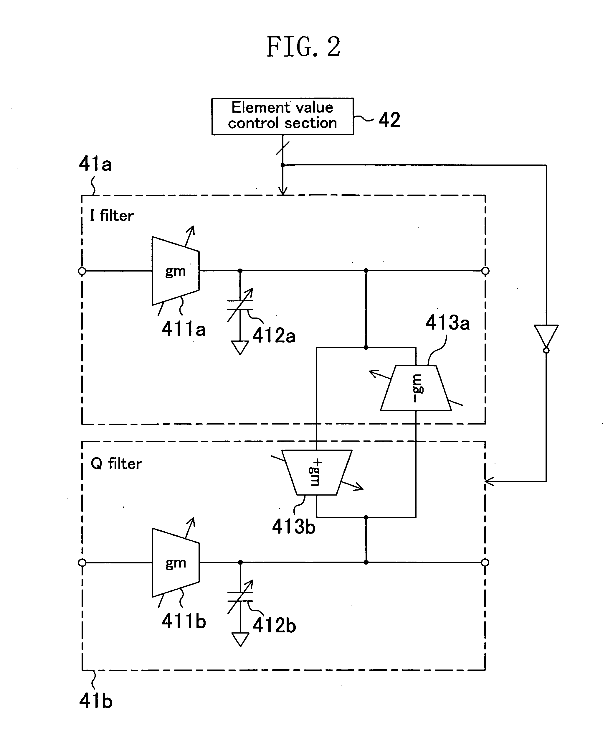
[0031]FIG. 2 shows a configuration of the complex filter circuit 40. The complex filter circuit 40 of the present embodiment generally includes a filter circuit 41a for processing an I signal, a filter circuit 41b for processing a Q signal, and an element value control section 42. The complex filter circuit 40 employs a Gm-C filter configuration, plac...

second embodiment

[0065]FIG. 8 shows a configuration of a receiver circuit according to a second embodiment of the present invention. The receiver circuit of the present embodiment is similar to that of the first embodiment except for how pseudo-image signals are produced and applied. Specifically, the receiver circuit of the present embodiment includes a pseudo-image signal producing section 200 and a signal switch 62. Other components are similar to those of the receiver circuit of the first embodiment. Therefore, those components and the operation of adjusting the element values of elements in the complex filter circuit 40 will not be further described below.

[0066] The quadrature demodulator 20 includes mixers 21a and 21b for performing a mixing operation on the received signals with local oscillator signals LO(I) and LO(Q) having phases shifted from each other by 90 degrees. In the receiver circuit of the present embodiment, a pseudo-image signal imitating an image signal that has not been quadr...

third embodiment

[0082] In view of the entire receiver circuit, the cause of an IQ mismatch lies not only in the complex filter circuit, and it can be said that any circuit preceding or following the complex filter circuit has an IQ mismatch to some extent. Some circuits may cause not only a gain error but also a phase error. For example, while local oscillator signals LO(I) and LO(Q) produced by a PLL, or the like, are ideally in a quadrature-phase relationship with each other, the phase relationship is somewhat shifted in practice. The shift leads to a shift in the phase relationship between the quadrature-demodulated I and Q signals. A mismatch between mixers in the quadrature demodulator is also a cause of a phase error. It is difficult to remove a phase error only with a complex filter circuit. Therefore, if there occurs a phase error as described above, it is difficult with the receiver circuits of the embodiments described above to sufficiently reduce the IQ mismatch.

[0083] In view of this, ...


PUM


Abstract

A pseudo-image signal producing section produces a pseudo-image signal imitating an actual image signal. An amplitude detection section detects the amplitude of the pseudo-image signal having passed through a complex filter circuit. A filter control section controls an element value control section in the complex filter circuit so as to decrease the detected amplitude. The element value control section performs an element value adjustment so that absolute element values of a pair of elements corresponding to each other in two filter circuits in the complex filter circuit increase / decrease in opposite directions.

Description

CROSS REFERENCE TO RELATED APPLICATION [0001] This application claims priority under 35 U.S.C. §119 on Patent Application No. 2004-311842 filed in Japan on Oct. 27, 2004 and Patent Application No. 2005-238422 filed in Japan on Aug. 19, 2005, the entire contents of which are hereby incorporated by reference. BACKGROUND OF THE INVENTION [0002] The present invention relates to a wireless communications system, and more particularly to a complex filter and a receiver circuit having the same. [0003] Typically, in a wireless communications receiver system of a superheterodyne architecture, such as a low-IF architecture, a complex filter circuit is used for removing an image signal. FIG. 14 shows a configuration of a conventional low-IF type receiver circuit. An LNA (Low Noise Amplifier) 10 amplifies a quadrature-modulated signal received via an antenna (not shown), or the like. A quadrature demodulator 20 performs quadrature modulation while downconverting the received signal, which has b...

Claims


Application Information

Patent Timeline
Patent Type & Authority Applications(United States)
IPC IPC(8): H04B1/10
CPCH04B1/123H04B1/30
Inventor MORIE, TAKASHIUENO, HIROYAFUJIYAMA, HIROKUNIHAYASHI, JOJIMATSUMOTO, AKINORIHIJIKATA, KATSUMASA
Owner PANASONIC CORP
Why Eureka
Try Eureka