Drug release coated stent

a technology of stents and coatings, applied in the field of expandable stent prostheses for therapeutic purposes, can solve the problems of reducing the cross-sectional area available for flow through the stent, reducing the relative amount of open space in the structure, and reducing the mechanical properties of metal stents of similar thickness and weaves. , to achieve the effect of axial deformation

Inactive Publication Date: 2006-04-27
BOSTON SCI SCIMED INC
View PDF99 Cites 66 Cited by
  • Summary
  • Abstract
  • Description
  • Claims
  • Application Information

AI Technical Summary

Benefits of technology

[0015] The present invention provides a relatively thin layer of biostable elastomeric material in which an amount of biologically active material is dispersed therein as a coating on the surfaces of a deployable expandable stent prosthesis. The preferred stent to be coated is a self-expanding, open-ended tubular stent prosthesis. Although other materials, including polymer materials, can be used, in the preferred embodiment, the tubular body is formed of an open braid of fine single or polyfilament metal wire which flexes without collapsing and readily axially deforms to an elongate shape for transluminal insertion via a vascular catheter. The stent resiliently attempts to resume predetermined stable dimensions upon relaxation in situ.

Problems solved by technology

Polymeric stents, although effective, generally cannot equal the mechanical properties of metal stents of like thickness and weave.
This, in turn, reduces the cross-sectional area available for flow through the stent and / or reduces the relative amount of open space available in the structure.
In addition, when applicable, it is usually more difficult to load such a stent onto catheter delivery systems for conveyance through the vascular system of the patient to the site of interest.

Method used


Image

  • Drug release coated stent
  • Drug release coated stent
  • Drug release coated stent

Examples


Embodiment Construction

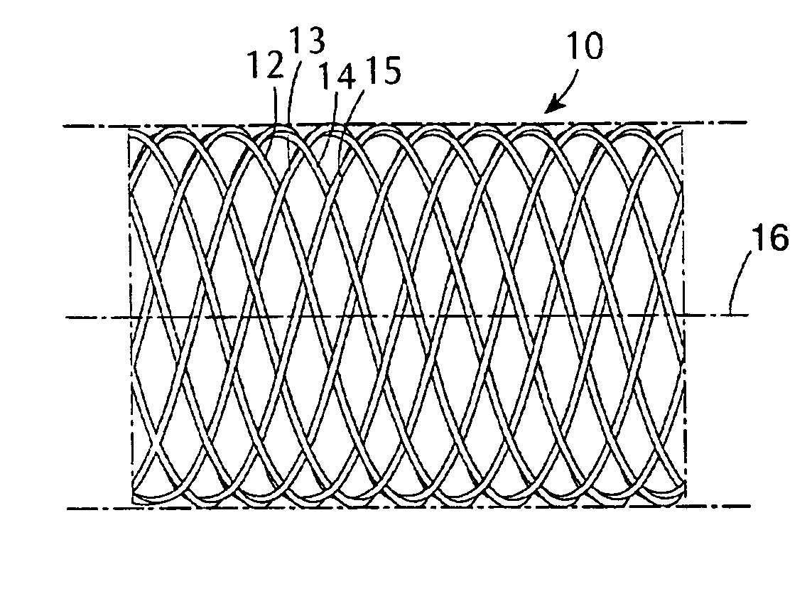
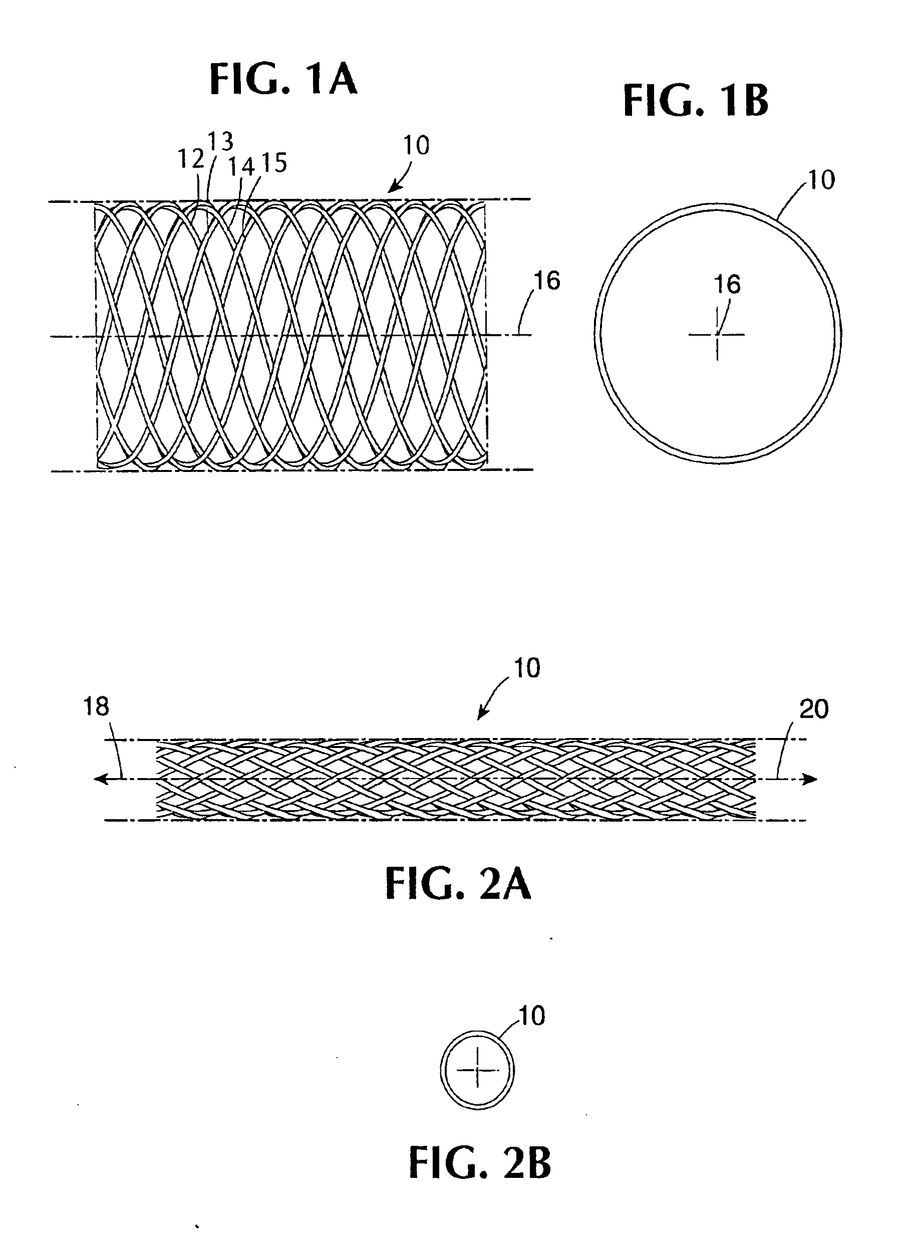
[0060] A type of stent device of one class designed to be utilized in combination with coatings in the present invention is shown diagrammatically in a side view and an end view, respectively contained in FIGS. 1A and 1B. FIG. 1A shows a section of a generally cylindrical tubular body 10 having a mantle surface formed by a number of individual thread elements 12, 14 and 13, 15, etc. of these elements, elements 12, 14, etc. extend generally in an helix configuration axially displaced in relation to each other but having center line 16 of the body 10 as a common axis. The other elements 13, 15, likewise axially displaced, extend in helix configuration in the opposite direction, the elements extending in the two directions crossing each other in the manner indicated in FIG. 1A. A tubular member so concerned and so constructed can be designed to be any convenient diameter, it being remembered that the larger the desired diameter, the larger the number of filaments of a given wire diamet...


PUM

PropertyMeasurementUnit
timeaaaaaaaaaa
thicknessaaaaaaaaaa
thicknessaaaaaaaaaa

Abstract

The present invention is directed to an expandable stent for implantation in a patient comprising a tubular metal body having open ends and a sidewall structure having openings therein and a coating disposed on a surface of said sidewall structure, said coating comprising a hydrophobic biostable elastomeric material and a biologically active material, wherein said coating continuously conforms to said structure in a manner that preserves said openings.

Description

CROSS-REFERENCE TO RELATED APPLICATION [0001] The present application is a Continuation application of co-pending U.S. patent application Ser. No. 10 / 022,607, filed on Dec. 17, 2001, which is Continuation-In-Part of U.S. patent application Ser. No. 09 / 079,645, filed May 15, 1998, which is a Continuation of U.S. patent application Ser. No. 08 / 730,542, filed Oct. 11, 1996, abandoned, which is a FWC of U.S. patent application Ser. No. 08 / 424,884, filed Apr. 19, 1995, abandoned; and co-pending U.S. patent application Ser. No. 10 / 022,607, filed on Dec. 17, 2001, is also a Continuation-In-Part of U.S. patent application Ser. No. 09 / 012,443, filed Jan. 23, 1998, which is a Division of U.S. patent application Ser. No. 08 / 663,490, filed Jun. 13, 1996, U.S. Pat. No. 5,837,313, which is a Continuation-In-Part of U.S. patent application Ser. No. 08 / 526,273, filed Sep. 11, 1995, abandoned, which is a Continuation-In-Part of U.S. patent application Ser. No. 08 / 424,884, filed Apr. 19, 1995, abando...

Claims


Application Information

Patent Timeline
Patent Type & Authority Applications(United States)
IPC IPC(8): A61F2/90A61F2/00A61F2/82A61F2/86A61L27/22A61L31/10A61L31/14A61L31/16
CPCA61F2/82A61F2/86A61F2/90A61F2210/0014A61F2250/0067A61L27/227A61L31/10A61L31/141A61L31/16A61L33/0011A61L2300/236A61L2300/416A61L2300/42A61L2300/43A61L2300/606C08L83/04
Inventor DING, NIHELMUS, MICHAEL
Owner BOSTON SCI SCIMED INC
Why Eureka
Try Eureka