Loop-back wavelength division multiplexing passive optical network

a passive optical network and wavelength division technology, applied in the field of wavelength division multiplexing passive optical network, can solve the problems of difficulty in providing a quality-guaranteed wide bandwidth of more than 100 mb/s to subscribers, difficulty in deployment, and difficulty in providing such dsl and cmts technologies with bandwidth and quality assurance, and achieves the effect of reducing power loss and simple structur

Inactive Publication Date: 2006-05-04
ELECTRONICS & TELECOMM RES INST
View PDF4 Cites 58 Cited by
  • Summary
  • Abstract
  • Description
  • Claims
  • Application Information

AI Technical Summary

Benefits of technology

[0011] Accordingly, the present invention has been made keeping in mind the above problems occurring in the prior art, and an object of the present invention is to provide a loop-back WDM-PON, which is capable of eliminating power los

Problems solved by technology

It is expected that it is difficult for such DSL and CMTS technologies to provide a bandwidth and a quality guarantee sufficient to provide voice, data and broadcast convergence service, which will be popularized within a few years, to subscribers.
In the two above-described types of FTTH networks, a data transmission optical transmission path is constructed on a single wavelength per transmission direction basis, which has a limitation in providing a quality-guaranteed wide bandwidth of more than 100 Mb/s to subscribers.
However, the WDM-PON requires light sources having multiple wavelengths the number of which is identical of that of subscribers, so that an economical burden is imposed on a telecommunications service provider and, therefore, there is difficulty in deployment.
Considering the maintenance of the network, the fact that the service provider must prepare different light sources having different wavelengths for individual subscribers may impose a burden on the service provider.
Howev

Method used


Image

  • Loop-back wavelength division multiplexing passive optical network
  • Loop-back wavelength division multiplexing passive optical network
  • Loop-back wavelength division multiplexing passive optical network

Examples


first embodiment

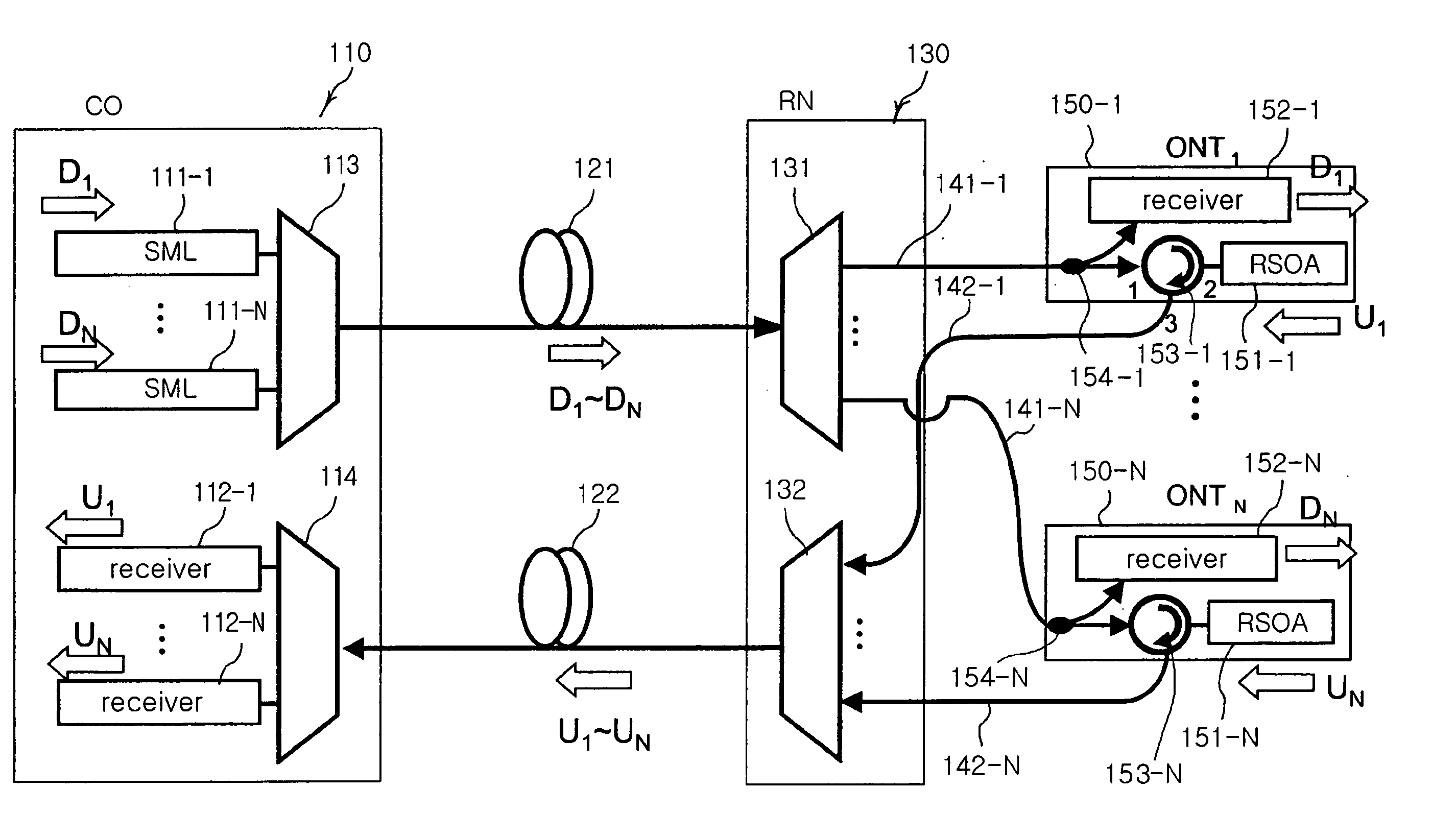
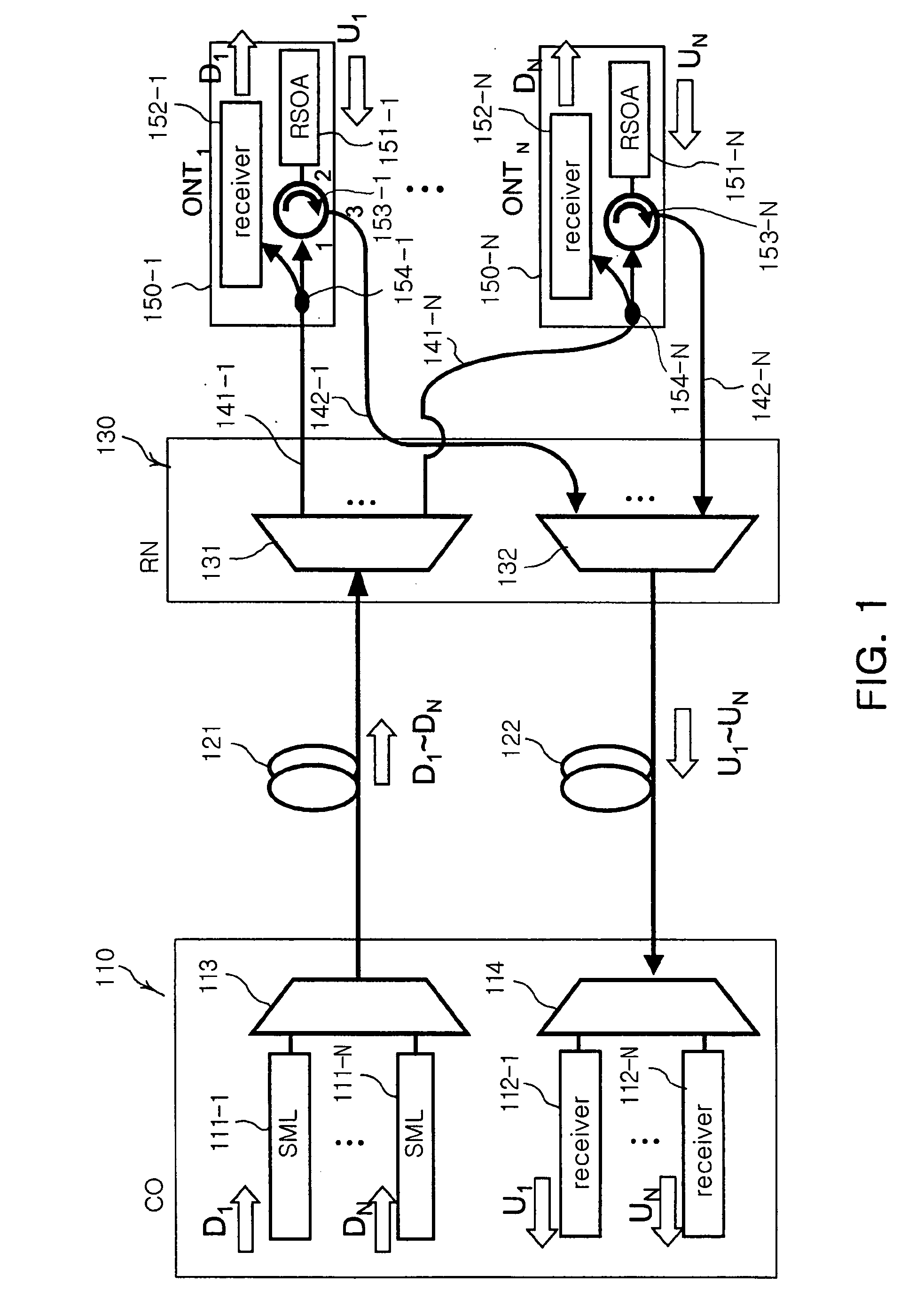
[0033]FIG. 1 is a diagram illustrating the configuration of a loop-back WDM-PON according to the present invention.

[0034] Referring to FIG. 1, an RSOA-based loop-back WDM-PON system according to the first embodiment of the present invention includes a central office (CO) 110, upstream and downstream optical fibers 121 and 122, a remote node (RN) 130, downstream signal optical fibers 141-1 to 141-N, upstream signal optical fibers 142-1 to 142-N, and optical network terminals (ONTs) 150-1 to 150-N.

[0035] The central office 110 includes light sources 111-1 to 111-N, central office receivers 112-1 to 112-N, a central office optical multiplexer 113, and a central office optical demultiplexer 114. For example, Single Mode Laser diodes (SMLDs), such as Distributed Feedback Laser Diodes (DFB-LDs), may be used as the light sources 111-1 to 111-N, and are constructed separately or in an integrated array form. The lights of single mode laser diodes, having N wavelengths that are assigned to t...

second embodiment

[0050]FIG. 4 is a diagram illustrating the configuration of a loop-back WDM-PON according to the present invention.

[0051] The loop-back WDM-PON according to the first embodiment of the present invention, which is shown in FIG. 1, has a structure in which the optical network terminals 150-1 to 150-N are provided with the couplers 154-1 to 154-N and the circulators 153-1 to 153-N, respectively, so that it is relatively expensive and has a somewhat complicated structure. In contrast, in the loop-back WDM-PON according to the second embodiment of the present invention, a coupler 134 and a circulator 133 are positioned in a remote node 130 and shared by subscribers, thus resulting in a structure that reduces the cost and complexity of constructing a network.

[0052] Referring to FIG. 4, in the loop-back WDM-PON according to the second embodiment of the present invention, a multiplexed downstream signal is input from a central office 110 to the remote node 130 through a downstream optical ...

third embodiment

[0054]FIG. 5 is a diagram illustrating the configuration of a loop-back WDM-PON according to the present invention.

[0055] The loop-back WDM-PON according to the second embodiment of the present invention, which is shown in FIG. 4, has a structure in which the upstream optical fiber 121 and the downstream optical fiber 122 are separately used, whereas the loop-back WDM-PON according to the third embodiment of the present invention is constructed to transmit both an upstream signal and a downstream signal through a single optical fiber.

[0056] Referring to FIG. 5, in the loop-back WDM-PON according to the third embodiment of the present invention, a circulator 115 is positioned in a central office 115, and a coupler 134 is positioned in a remote node 130. The outputs of single mode light sources 111-1 to 111-N modulated to a downstream signal in the central office 110 are multiplexed by an optical multiplexer 113, and input to the remote node 130 through the circulator 115 and an upst...


PUM


Abstract

Disclosed herein is a loop-back Wavelength Division Multiplexing Passive Optical network (WDM-PON). The loop-back WDM-PON includes a coupler, a terminal receiver, and a reflective semiconductor amplifier. The coupler branches a downstream signal, which is transmitted from a central office, into first and second downstream signals. The terminal receiver receives and converts the first downstream signal into electrical signal and provides the electrical signal to a subscriber. The reflective semiconductor optical amplifier flattens modulated optical power of the second downstream signal input to the RSOA and re-modulating the flattened signal by changing driving current in response to upstream data.

Description

RELATED APPLICATIONS [0001] The present application is based on, and claims priority from, Korean Application Number 2004-0086570, filed Oct. 28, 2004, the disclosure of which is incorporated by reference herein in its entirety. BACKGROUND OF THE INVENTION [0002] 1. Field of the Invention [0003] The present invention relates generally to a wavelength division multiplexing passive optical network and, more particularly, to a loop-back passive optical network. [0004] 2. Description of the Related Art [0005] Currently, a Digital Subscriber Line (DSL) technology using an Unshielded Twisted Pair (UTP) and a Cable Modem Termination System (CMTS) technology using a Hybrid Fiber Coaxial (HFC) network have been widely used as information transmission technologies for communication systems. It is expected that it is difficult for such DSL and CMTS technologies to provide a bandwidth and a quality guarantee sufficient to provide voice, data and broadcast convergence service, which will be popu...

Claims


Application Information

Patent Timeline
IPC IPC(8): H04J14/00
CPCH04B10/2587H04J14/02H04J14/0226H04J14/0282H04J14/0246H04J14/025H04J2014/0253H04B10/035H04B10/2581
Inventor KIM, BYOUNG WHILEE, WOO RAM
Owner ELECTRONICS & TELECOMM RES INST
Why Eureka
Try Eureka