Resid cracking apparatus with catalyst and adsorbent regenerators and a process thereof

a cracking apparatus and adsorbent technology, applied in the direction of catalytic cracking, hydrocarbon oil treatment, liquid hydrocarbon mixture production, etc., can solve the serious problem of residue processing capability of fcc unit, reduce catalyst/oil ratio to maintain heat balance of fcc unit, and bring down catalyst activity and selectivity, etc. problem, to achieve the effect of enhancing the life of the apparatus, reducing the cost and increasing production

Inactive Publication Date: 2006-05-11
INDIAN OIL CORPORATION
View PDF14 Cites 24 Cited by
  • Summary
  • Abstract
  • Description
  • Claims
  • Application Information

AI Technical Summary

Benefits of technology

[0017] Yet another object of the present invention is to provide longevity to the catalyst, thereby increasing the production by lowering the cost.
[0018] Still, yet another object of the present invention is to provide a compatible design for said apparatus so that it can be used also with other FCC designs.
[0019] Another object of the present invention is to enhance the life of the apparatus by controlling the operating temperatures optionally by using catalyst coolers.

Problems solved by technology

The high CCR of the feed tends to form coke on the catalyst surface, which in turn brings down the catalyst activity and its selectivity.
Moreover, the higher deposit of coke on the catalyst increases the regenerator temperature and therefore catalyst / oil ratio reduces to maintain the heat balance of FCC unit.
These above limits pose serious problem of residue processing capability of FCC unit.
However, even with two-stage regenerator of U.S. Pat. No. 4,064,038, there is limitation to increase feed CCR above 4.5-wt % and vanadium above 15-20 PPM on feed.
Though such a process is simple, there are several practical disadvantages, which limit its resid-handling capability, namely (I) the regenerator is kept in the dense phase where the average superficial velocity is about 0.7 meter / second.
Moreover, there is a sufficient turbulence and mixing in the bed, which leads to poor segregation efficiency (II) it is known in the FCC art that vanadium is highly mobile in the regenerator atmosphere, and that too in the single stage regenerator, the vanadium may escape from the demetallizing additive to the catalyst particle at these conditions.
This defeats the basic purpose of eliminating catalyst deactivation due to metal poisoning.
However, the mobile vanadium vapors are allowed to move to the high temperature regenerator through lift line along with the catalyst, which may cause considerable damage to zeolite in the catalyst particles.
As the additive cooler is provided at downstream of first stage regenerator, it is difficult to control dense bed temperature, which will further aggravate the destruction of zeolite structure.
The attrition resistance will be poor with such coarse particles.
However, these inventions do not address the issues related to minimization of metal deactivation of catalyst and removal of feed CCR as arises in residue processing in FCC.
Moreover, this patent does not address the issues pertaining to the problems of avoiding CCR and metal deactivation of catalyst while processing residue in FCC units.
As the segregation and regeneration of sorbent and catalyst is carried out in first stage regenerator, the vanadium may migrate from the sorbent to the catalyst particle and destroy zeolite structure of the catalyst at such high temperature conditions.

Method used


Image

  • Resid cracking apparatus with catalyst and adsorbent regenerators and a process thereof
  • Resid cracking apparatus with catalyst and adsorbent regenerators and a process thereof
  • Resid cracking apparatus with catalyst and adsorbent regenerators and a process thereof

Examples


example 1

[0130] This example illustrates the relationship between superficial gas velocity and segregation efficiency in the said apparatus. Two types of particles i.e. sand of particle size in the range of 210-350 microns with particle density of 2.6 g / cc and catalyst of size in the range of 40-150 microns with particle density of 1.45 g / cc are used in this study.

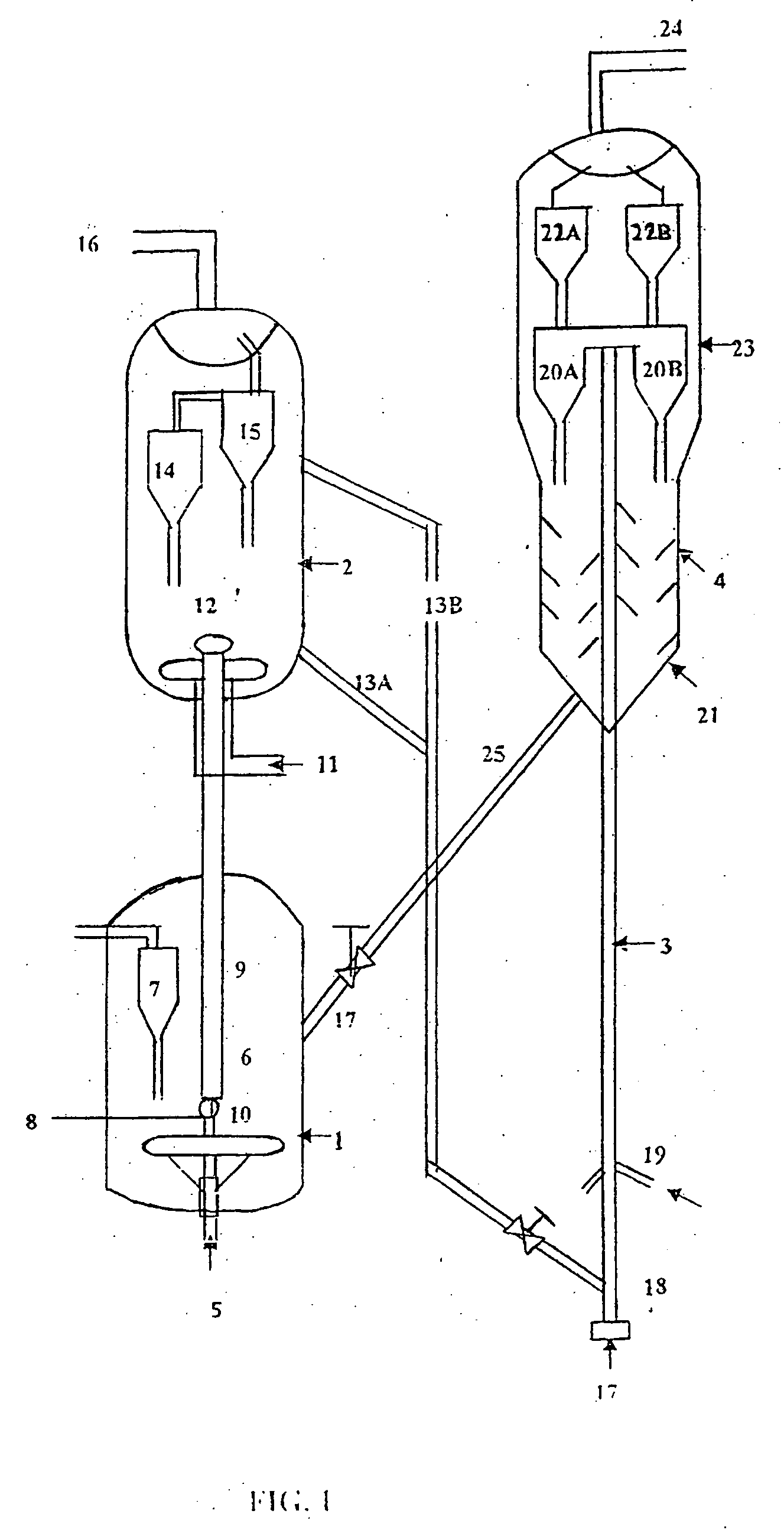
[0131] The apparatus is a circulating fluidized bed system consisting of a riser of diameter 6″ and of length 280″, having two stage cyclone system for gas-solid separation and a separator vessel of diameter 20″ ID and length of 100″ with a provision for introduction of gas through distributor from its base and an entry for receiving catalyst-sand mixture, an outlet for taking out the catalyst via upper stand pipe having flow communication with intermediate location in the riser, containing another outlet for sand withdrawal at the bottom of separator vessel and having connected to riser via lower stand pipe.

[0132] The sequence o...

example 2

[0137] This example illustrates the benefits of sequential dual solid processing particularly the vanadium deposition preferentially on the adsorbent particles and thereby improving the activity of the FCC catalyst.

[0138] For this purpose following samples are considered.

[0139] Catalyst-A Commercially available ReUSY (rare earth exchanged ultra stable Y) based FCC catalyst sample.

[0140] Adsorbent-B V-trap commercial additive with particle size in the range of 250-350 micron.

[0141] Vanadium is first deposited (by adopting pore volume impregnation route of Mitchell) at 0 and 10,000 ppm on the mixture of catalyst A and adsorbent B, mixed in the ratio of 10:0.6.

[0142] Typically, the MAT activity was determined using MAT (micro activity test) at 510° C. reactor temperature, 2.5 grams solid loading, 30 seconds feed injection time and varying feed rate to generate data at different conversion levels. Feed used is the combined feed used in one commercial FCC unit with CCR 0.4 wt %, boi...


PUM

PropertyMeasurementUnit
temperatureaaaaaaaaaa
residence timeaaaaaaaaaa

Abstract

This invention provides a resid cracking apparatus comprising a riser, reactor, stripper cum separator with adjustable outlets in flow communication with adsorbent and catalyst regenerators for converting hydrocarbon residues containing higher concentration of conradson carbon content, poisonous metals such as nickel & vanadium and basic nitrogen etc., into lighter and valuable products and a process thereof.

Description

FIELD OF THE INVENTION [0001] This invention relates to a resid cracking apparatus comprising a riser, reactor, stripper cum separator adsorbent and catalyst regenerator for converting hydrocarbon residues containing higher concentration of conradson carbon content, poisonous metals such as nickel & vanadium and basic nitrogen etc., into lighter and valuable products and a process thereof. BACKGROUND AND PRIOR ART OF THE INVENTION [0002] Fluid Catalytic Cracking (FCC) is one of the key processes employed in petroleum refineries for converting heavy vacuum gas oil into lighter products namely gasoline, diesel and liquefied petroleum gas (LPG). Processing of heavy residues e.g. atmospheric and vacuum bottoms are increasingly being practiced in the FCC Unit for enhanced conversion of residue. Heavy residues contain higher amount of Conradson carbon residue (CCR), poisonous metals e.g. sodium, nickel, vanadium and basic nitrogen compounds etc., all of which have significant impact on th...

Claims


Application Information

Patent Timeline
Patent Type & Authority Applications(United States)
IPC IPC(8): C10G11/00
CPCC10G11/18C10G25/05C10G25/08C10G55/06
Inventor PANKAJ, KAWLIWALMARRI, RAMA RAOKUMAR, DIXIT JAGDEVLAL, SAROYA LATOORMANDAL, SUKUMARMAKHIJA, SATISHGHOSH, SOBHAN
Owner INDIAN OIL CORPORATION
Why Eureka
Try Eureka